


white
black
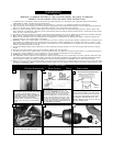
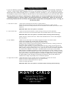
Make wiring connections as indicated above.
White from fan to white from remote marked
N. Orange from fan to Orange from remote
marked Light/up. Blue from fan to blue from
remote marked down light. Black from fan to
Black from remote marked L. White from
house to white from remote marked AC N .
Black from house to Black from remote
marked AC L. Connect all green ground wires
to Ground wire from House.
Install remote receiver by sliding into opening in
the Mounting bracket. Make sure that the dip
switches on the Transmitter and the Receiver
are set to the same position. See Fig 37 for
remote operation
Set dip switches on the Remote Transmitter and Remote
Receiver to the same settings. This must be done so the
units will communcate properly. If you have other fans you
can set to control from one transmitter by setting both
receivers the same as the transmitter. If you have more
than one fan with remote. You can set the dip switches to
different positiosns to have seperate control.
Remote Transmitter Dip swtiches
Remote Receiver Dip switches
orange
blue
Green
white
black
House
Fan
21
22
24
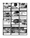
Lift Canopy to ceiling aligning the key hole slots
with the screws on the bottom of the Mounting
bracket. Rotate the canopy Counter Clockwise
to lock in place. Tighten the screws to secure
the Canopy. See inset for Keyhole shape
25
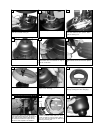
Make wire connections to power source using
wire nuts provided. Make sure that no filiments
are outside of the wirenut. After making the
wire connections, the wires should be spread
apart with the grounded conductor and the
equipment-grounding conductor on one side of
the outlet box and ungrounded conductor on
the other side of the outlet box.
23
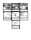
Raise fan with downrod assembled to
the ceiling bracket and hang fan
assembly. Be sure to rotate the
downrod ball so that the notch in the
bracket engages the slot in the ball
and the bracket slides shut.
19
With the bracket shut (see # 23) start the two
screws do not tighten at this time.
20
Check the motor for plastic shipping stabi-
lizer tabs and remove them if they are
present. The screws, washers, and motor
pads are pre-installed to the blade brack-
ets. Attach blade assembly to motor and
tighten screws securely.
Find wires from lower light and fan body.
Plug wires together as follows. Connect
blue wire from fan to black wire from
light. Connect white wire from fan to
white wire from light.
26
28
Remove one screw and loosen the other
two screws.
29
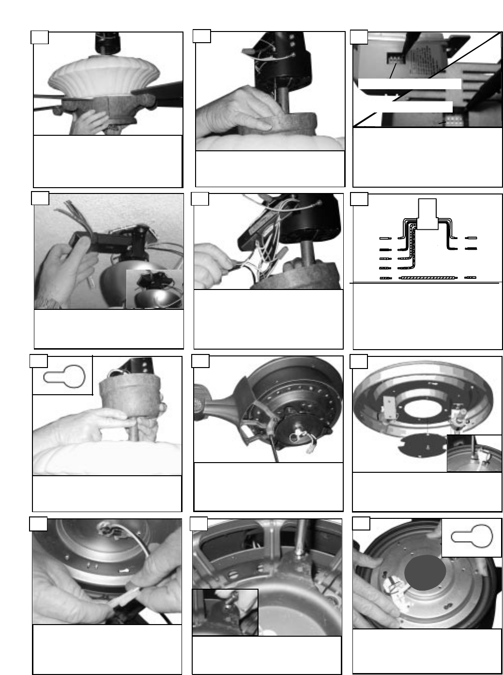
Lift light kit pan to the fan motor assembly.
Align the 2 screws with the key slot holes in the
light kit pan (see insert). Rotate the light kit pan
as shown. Then install the screw removed in
the previous step through the closed hole.
Tighten all 3 screws securely.
30
Remove inspection plate from light kit
pan.
27