


27D8520 9
Label all wires prior to disconnection
when servicing controls. Wiring errors
can cause improper and dangerous
operation. Verify proper operation after
servicing.
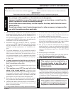
WARNING
Do not connect to 110 volt supply.
WARNING
Keep wiring away from heat
source and hot surfaces.
WARNING
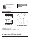
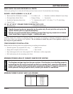
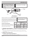
THTP
TP
TH
Milli-volt
Valve
Pilot
WIRING (MILLI-VOLT)
Figure 7 - Wiring Diagram
The Milli-Volt (thermopile) is a self powered combination gas con-
trol that does not require 110VAC to operate. Refer to Figure 8 and
installation instructions provided with optional wall switch or remote
control for wiring instructions. A maximum length of 15 feet of 18awg
two conductor wire is to be used for wall switch. Note switches must
be suitable for millivolt operation. The optional wall switch must be
mounted outside the firebox. The remote receiver location must not
exceed a temperature of 120 F.
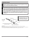
CHECKING SYSTEM OPERATION
The milli-volt system and individual components may be
checked with a millivolt meter having a 0-1000MV range.
Conduct each check shown in chart below by connection
meter test leads to terminals as indicated.
A. COMPLETE MILLI-VOLT SYSTEM CHECK
("A" READING - CONTACTS CLOSED - CONTROL KNOB "ON" - MAIN BURNER SHOULD BE COME
ON)
a. If the reading is more than 100 millivolts and the automatic valve still does not come on - replace the control.
b. If the closed circuit reading (“A” reading) is less than 100 millivolts, determine cause for low reading —
proceed as follows:
B. THERMOPILE OUTPUT READING CHECK
(“B” READING - CONTACTS OPEN - MAIN BURNER OFF)
a. 325 millivolts minimum. If the minimum millivolt reading is not obtainable, readjust pilot for maximum millivolt
output. If millivolt reading is still below minimum specified, replace thermopile.
CONNECT
METER METER
CHECK TO LEADS TO READING
TEST TEST TERMINALS SHOULD BE
A COMPLETE TH & THTP Min. 100 mV
SYSTEM
B THERMOPILE TP & THTP Min. 325 mV
OUTPUT
Optional Wall Switch
or Remote Reciever
Switch