


22 81D0107
ELECTRICAL WIRING (MILLIVOLT)
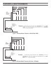
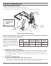
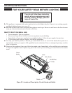
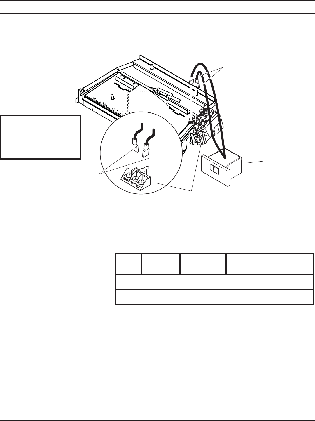
CONNECTING REMOTE RECEIVER
1. Set remote receiver. See instructions included in receiver kit.
2. Connect the two (2) 1/4" female connectors to the TP/TH and TH terminals on the control valve.
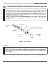
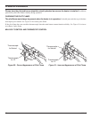
Figure 18 - Installing Remote Receiver
Remote
Receiver
Remote
Wire
Connectors
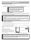
A. COMPLETE MILLIVOLT SYSTEM CHECK
(“A” Reading - Thermostat contacts CLOSED - Control Knob “ON” - Main burner should turn ON)
a. If the reading is more than 175 Millivolts and the automatic valve still does not come on, replace the control.
b. If the closed circuit reading (“A” reading) is less than 175 Millivolts, determine cause for low reading, proceed to
Section B below.
B. Thermopile Output Reading Check
(“B” Reading - Thermostat contacts OPEN - Main burner OFF)
1. Check gas pressure to the unit. If gas pressure is within minimum and maximum on data plate, then check pilot
voltage, 500 Millivolts minimum. If the minimum Millivolt reading is not obtainable, replace pilot.
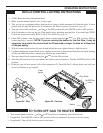
CHECKING SYSTEM OPERATION
The Millivolt system and individual com-
ponents may be checked with a Millivolt
meter having a 0-1000 mV range. Con-
duct each check shown in chart below by
connection meter test leads to terminals
as indicated.
CHECK
TEST TO TEST
CONNECT
METER LEADS
TO TERMINALS
SWITCH OR
THERMOSTAT
CONTACTS
METER
READING
SHOULD BE
A
COMPLETE
SYSTEM
2 & 3 CLOSED MINIMUM 175
B
THERMOPILE
OUTPUT
1 & 2 OPEN MINIMUM 500
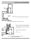
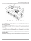
Note: Heat reduces battery life. You can protect the receiver and extend battery life by mounting receiver
in wall or other location outside the fi replace.
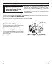
Remote
Wire
Connectors
Valve
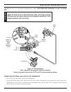
NOTICE
Do not let wires
touch grate or
burner.