


73D0024
25
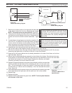
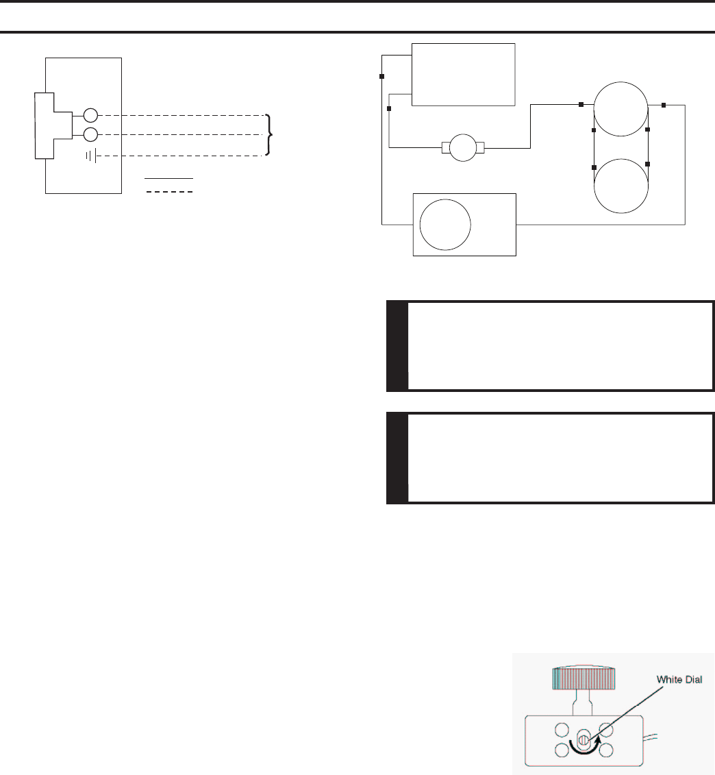
KHLDV Series Gas Fireplace
Junction Box
Blower
Rheostat
T-Stat Sensor
Right
Blower
Left
Blower
White
Black
Hi-Temp
Black
Black
Hi-Temp
Black
Black
FP2135
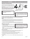
blower wiring diagram
Blue
Blue
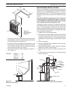
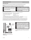
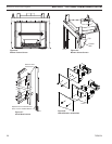
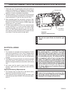
7. Remove the access covers on the right and left side walls
of the firebox toward the front by unfastening the screws.
Figure 35
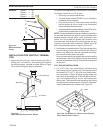
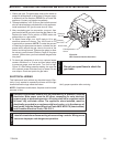
8. Two screws are already mounted to each cover which would
be utilized to mount the blower to the cover. Unfasten the two
screws and mount the blower bracket assemblies. Figure
37
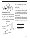
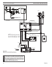
9. Consult blower wiring diagram and start the assembly. Fig-
ures 32 & 33. It is helpful to wire the right blower, the speed
control, the fan limit switch, and the power cord first. Then
plug in the power cord to the junction box and secure the right
cover plate/blower assembly to the side of the firebox.
10. Assemble the wire clips provided with the blower kit to the
right and left sides of the fireplace through existing holes on right and left.
11. Run the wire harness down the right and snap wires into the clips assembled in #10. Run the two
wires along the glass track, on the floor of the unit, in front of the firebox
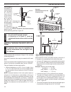
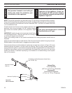
12. Snap the fan limit switch behind the clip already assembled to the side of the firebox on the front
right hand side. Figure 36
13. Secure the left access plate/blower assembly to the left side of the firebox. Run the two wires men-
tioned earlier up the left firebox wall and snap wires into clip assembled in #10 on the outer shell
wall. Make the connection to the left blower. Replace the refractory and hearth
refractory (pull away from burner toward the front).
14. Replace side panels attached to the glass frame assembly with the louvered side
panels provided with the blower kit by unfastening the four nuts for each cover
door. (Do not overtighten or stud may break off.) Use three metal clip screws
provided with kit to secure the wire assembly in the front beneath the access
cover. Figure 36
15. Install the speed control (rheostat switch) on the side above the existing one used
for the light (discard the plate sent with the switch as it will not be needed.
16. Replace logs.
17. Replace the glass.
18. Replace the front plate below the glass frame.
Figure 33 -
Blower Wiring Diagram
FP1912
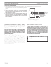
Junction box wiring
8/08
120V AC
60Hz
Factory Supplied
Not Supplied
Figure 32 -
Junction Box Wiring Diagram
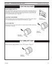
Figure 34 -
Location of White Dial on
Speed Control
Electrical Grounding Instructions: This appli-
ance is equipped with a three-prong (grounding)
plug for your protection against shock hazard
and should be plugged directly into a properly
grounded three prong receptacle.
Failure to replace the access cover with the one
provided with the blower kit, and then running
the blower, will cause excessive temperatures
and could cause a fire, property damage and/or
loss of life.