


17
53D9052
624WBPF Woodburning Fireplace
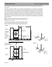
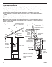
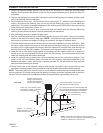
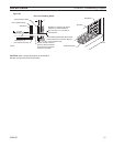
1. Extend the regular chimney sections until the top of the chimney is 4” below the total flue height
desired. Do not snap the last section of inlet air duct or largest diameter pipe in place until Step 3 is
completed.
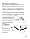
2. Remove the shingles from around the chimney so that the flashing may be installed, with the upper
part of the flashing under the shingles.
3. Set the flashing on the roof. Hold a section of the outside pipe (13” diameter) on the flashing and
scribe a line around the flashing, then cut the top off the flashing by cutting 1/4 inch below the
scribed line. This should increase the diameter of the flashing outlet sufficiently to allow the flashing
to be placed over the chimney. Figure 19
4. Snap the last section of inlet air duct in place and slide the flashing over the chimney. Adjust the
chimney to assure that the proper minimum clearances are maintained.
5. Nail the flashing securely in place with eight nails.
6. Seal the crack between the top of the flashing and the chimney with mastic. Leave some excess
mastic at this area to be used in step eight. Use pliers and wear gloves when performing
step seven to minimize the danger of cutting your hands on the edge of the storm collar.
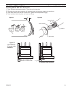
7. Place the storm collar around the chimney and put the collar together like a belt in belt loops. Slide
the end of collar under the two loops on the other end with the loops facing up. Overlap the ends of
the collar until it is tight against the chimney. Bend the free end of the collar back over the loops to
hold the storm collar securely together. The excess end of the storm collar may be trimmed off.
8. Slide the storm collar down snugly against the flashing until the excess mastic left in step six is
forced up into the crack between the storm collar and the chimney. This should make the joint be-
tween the flashing and the chimney watertight.
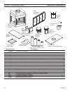
9. Install the chimney cap by placing the cap into matching parts of the last chimney section. Then
punch or drill 1/8 inch diameter holes in the inlet air duct (chimney pipe) where specified on the
brackets and fasten it down with the No. 8 screws provided. Do not penetrate the inner stainless
steel pipe while installing the screws.
10.Check all the parts of the fireplace, chimney and chimney termination cap to assure that no parts
have been damaged or bent during installation and that all parts have been installed properly.
The metal used for the chimney cap has a rust protective coating but the cut edges of the parts
are not protected. To prevent rusting and rust staining of nearby structures, exposed parts of the chim-
ney and chimney cap should be detergent washed and painted with a galvanized primer paint.
156O” Min.
Overlap
2” Min.
FP1899
chimney cap
8/08
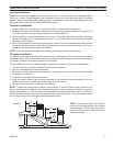
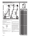
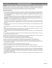
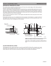
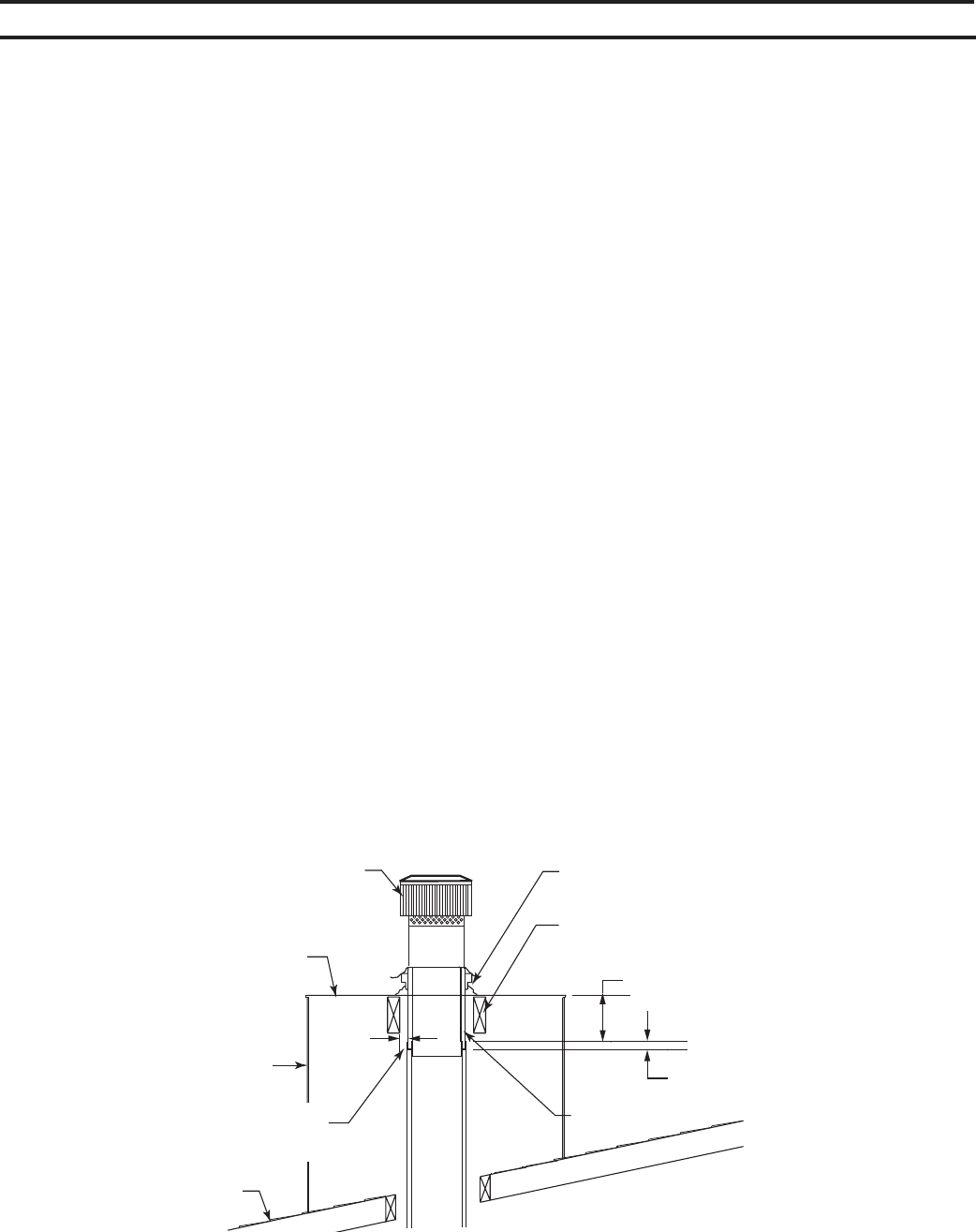
RLTCF11 Chimney Cap
Design Incorporates Lon-
ger Duct and Flue Pipe for
Chase Type Installation
Chase Top Flat Flashing Does
Not Require Venting or Standoff
Spacers Around Perimeter
Chase
Roof Line
Maintain 2” Minimum Air
Space Clearance to Combus-
tibles Above Roof Line
Using Tabs Provided, Secure Outer
Telescoping to the Flat Flashing
On Large Chase Tops it is Recommended that
Cross Supports be used to Provide Additional
Support to Eliminate Sagging of the Flashing
13” Max. Space Between Chimney
Section and Chase Cover
Outer Telescope
Locally built chase flashings must incorporate a
13Z\₄ min. to 13³\₄ max. x 2” high min. flanged hole for proper
installation of the RLTCF11 chimney cap.
Figure 20
FP1899