


13
53D9052
624WBPF Woodburning Fireplace
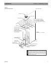
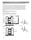
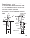
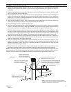
1. Lay out, cut and frame openings through all ceilings and the roof at the point where the chimney will pass
through. Unless the chimney is to be offset, the point where the center line of the chimney will pass through the
ceiling and roof can be determined with a plumb line as shown in Figure 10. The fireplace should be located in
the planned installation position. After the center line is established and a nail is driven to mark the point, the
opening can be cut if you are satisfied with the chimney location relative to ceiling and roof joists and/or any other
obstructions. The roof opening center line should be marked by driving a nail through the roof from underneath
that will penetrate the roof and can be located from the rooftop. If the chimney is to penetrate a pitched roof, the
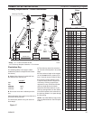
hole in the roof must be rectangular instead of square and should be sized according to Table1.
2. Install the firestop spacer as required from beneath the ceiling unless the space above is attic space. In an attic,
the firestop spacer should be installed at the floor level of the attic. You must have joists or headers on all four
sides of the spacer and use a minimum of four 8-penney nails to secure the spacer.
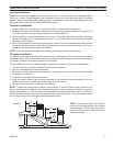
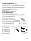
3. To install the chimney sections, insert the male end of the flue, the smallest diameter pipe, into the flue outlet of
the fireplace and press down until the snap locks engage. Continue the process, adding the chimney sections
on top of each other until the chimney is at least six inches above the roof opening on all sided. As the chimney
sections are installed, check each joint to make sure it is properly locked to the previous section. If additional
strength of the outer pipe joints is desired, you may use two or three sheet metal screws placed through the area
where the outer pipes overlap one another. To install these screws, drill a 1/8-inch diameter hole through the
chimney sections, taking care not to penetrate the inner flue pipe. Be very careful when drilling the
holes into the outer pipe. The drill must not penetrate the inner stainless steel pipe.
If you intend to have a total fireplace installation of more that 30 feet you must use chimney support model
11CS at or below 30 feet to support the weight of additional chimney pipe.
To install the chimney support, place the crimped end of the flue and outlet air duct portions into the last section
of chimney pipe. Push down until the outside or inlet air duct of the chimney support overlaps and snap locks the
chimney support into the chimney section.
Nail the support straps tightly to a building frame member or ceiling joist as shown by Figure 14. You must use at
least two 8-penney nails per strap.
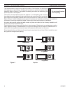
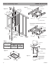
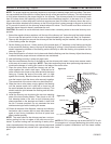
The following are important points that should be observed
when installing elbows on the fireplace:
1. The support straps of all elbows not installed directly on
top of the fireplace should be nailed securely to the sur-
rounding structure. This allows the support strap to carry
the weight of the chimney above the elbow and prevents
this weight from breaking the elbow or chimney sections
apart.
2. Elbows should not be used in any combination that in-
clines the chimney more than 30 degrees from vertical.
3. The limitations on the quantity of elbows per chimney are
as follows: If the total height of the fireplace and chimney
is—13’ or more — two (2) elbows may be used in the
chimney. 21’ or more — four (4) elbows may be used in
the chimney.
4. The inclined portions of chimneys that pass through liv-
ing spaces likely to be used for storage should be enclosed to avoid contact with and possible damage to the
chimney. The minimum air space of 2” between the chimney and enclosing materials must be maintained.
5. The length of the inclined portion of chimney between elbows must not exceed 6’ when unsupported or 20’ if the
chimney is supported at 6’ intervals with support such as metal support straps.
6. When enclosing the elbows and inclined portions of the chimney, enclosing materials must be installed vertically
to maintain the required 2” minimum air space clearance to the chimney at the extremities of the offset. It is
recommended that enclosing material not follow the inclined portions of the chimney.
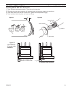
FP1893
30 elbow
8/08
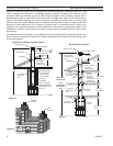
Figure 14
Inlet Air
Pipe
Flue
All four (4) support straps must be nailed on to framing member
around the elbow with a minimum of two (2) 8-Penny nails per
strap
Although both halves of the elbow set may have tie
straps, only the top half must be secured. The bottom elbow half
is not required to be secured for added stabilization of pipe.
FP1893