


5
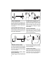
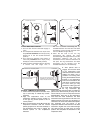
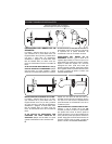
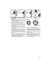
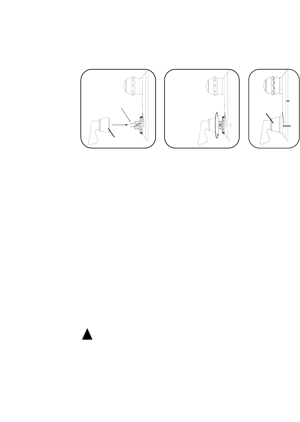
ATTACH FLOW HANDLE:
1. Confirm that the white flow extension is turned fully clockwise. Align the flow handle (7) to the
flow extension with the handle pointing downwards (6 o’clock position).
2. Move the flow handle towards the flow extension until the internal splines in the flow handle start
to engage the external splines on the flow extension.
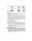
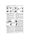
3. After the splines start to engage, turn the shell of the flow handle (7) clockwise several turns
while holding the handle to prevent it from rotating. This turning will thread the internal threads
in the flow handle onto the threads on the valve body. Continue turning the shell (you may
release the handle) until it compresses the ring escutcheon (5) against the base escutcheon (4).
It is helpful to pull the shell towards you (away from the shower wall) as you turn it to keep the
knob from disassembling. Again, as the flow handle nears the base escutcheon, the ring
escutcheon will have to be shifted upwards so that the ring escutcheon is centered on the lower
shell. Tighten the shell hand-tight only. This completes the attachment of the flow handle. The
valve trim is now completely assembled and is ready for operation.
Flow extension turned
fully clockwise
Use your hand to center the ring
escutcheon as the handle is
threaded onto valve stem.
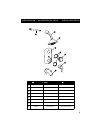
7
7
5
4
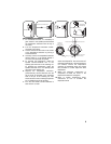
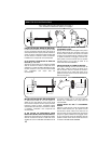
TESTING FOR PROPER OPERATION:
1. Make sure the flow handle (7) is still in the full down 6 o’clock position.
2. Turn on the hot and cold water supplies.
3. Turn the temperature knob fully counterclockwise so the number “9” is in the vertical 12 o’clock
position. The numbers represent increasing temperature. “9” is the hottest and “1” is the coldest.
4. Turn the flow handle counter-clockwise to start flow from the shower head or tub spout.
5. The thermostatic valve has a temperature range from 85°F (29°C) corresponding to the number
“1” on the temperature knob to 115°F (46°C) corresponding to the number “9” on the temperature
knob. If the temperature when the knob is set at “9” is not approximately 115°F (46°C), or if a
hotter maximum temperature is desired, the temperature range can be recalibrated by following
the instructions in the section “Recalibration Procedure.”
NOTE: Recalibration to a higher maximum temperature will increase the temperature
across the entire range.
CAUTION: RISK OF SCALDING HAZARD
The valve has been calibrated at the factory to provide a maximum water temperature
of 115°F (46°C). Any significant variation in the calibration or any variation in the water
supply temperatures (greater than 5°F or 3°C) from those used at the factory during
the calibration procedure can result in water temperatures that present scalding
dangers. Therefore, it is important to check the water temperature with the
temperature knob set at “9” to determine the maximum temperature of the water. The
responsibility for the proper installation and any recalibration of this valve lies with the
installer.
6. Turn the water off by turning the flow handle fully clockwise.
!