


9
7. Electrical work
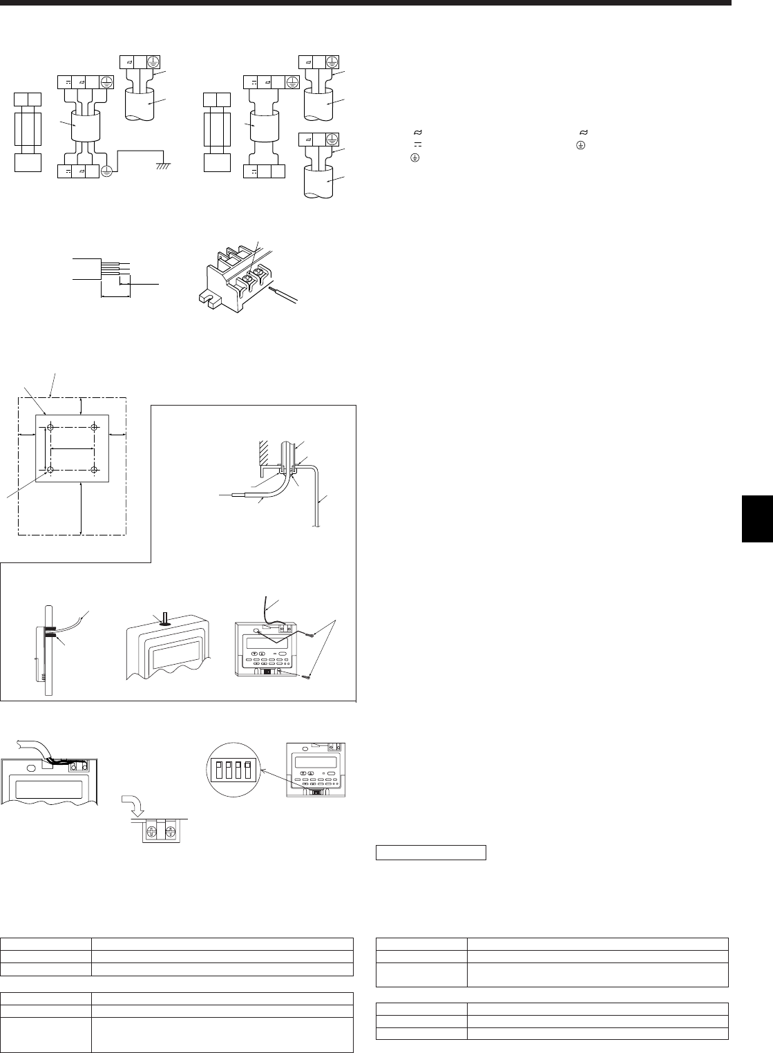
Fig. 7-4
LN
N
2 3
N
2 3
1
2
5
12
7
6
3
4
65 mm
15 mm
1
2
Fig. 7-3
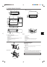
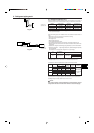
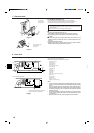
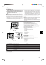
• Perform wiring as shown in the diagram to the lower left. (Procure the cable lo-
cally). (Fig. 7-3)
Make sure to use cables of the correct polarity only.
1 Connecting cable 2 Power supply cable
4 core VVF cable 3 core with ground IEC cord
• SEZ-A12:1.0 mm
2
or more • SEZ-A12:1.0 mm
2
or more
• SEZ-A18, A24:1.5 mm
2
or more • SEZ-A18, A24:1.5 mm
2
or more
Colors Colors
N : Blue N : Blue
2 : Brown L : Brown
3 : Red : Green/Yellow
: Green/Yellow
3 Indoor
4 Outdoor
5 Always install an earth longer than other cables
6 Remote controller cable
Wire No × size (mm
2
) : Cable 2C × 0.69
This wire accessory of remote controller
(wire length : 10m, non-polar)
7 Remote controller
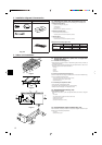
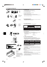
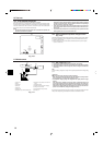
• Connect the terminal blocks as shown in the diagram below. (Fig. 7-4)
1 Loosen terminal screw
2 Terminal bed
(1) Use care not to make mis-wiring.
(2) Firmly tighten the terminal screws to prevent then from loosening.
(3) After tightening, pull the wires lightly to confirm that they do not move.
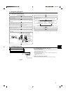
7.3. Remote controller
7.3.1. For wired remote controller
1) Installing procedures
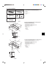
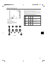
(1) Select an installing position for the remote controller. (Fig. 7-5)
The temperature sensors are located on both remote controller and indoor unit.
s Procure the following parts locally:
Two piece switch box
Thin copper conduit tube
Lock nuts and bushings
A Remote controller profile
B Required clearances surrounding the remote controller
C Installation pitch
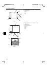
(2) Seal the service entrance for the remote controller cord with putty to prevent
possible invasion of dew drops, water, cockroaches or worms. (Fig. 7-6)
A For installation in the switch box:
B For direct installation on the wall select one of the following:
• Prepare a hole through the wall to pass the remote controller cord (in order to run
the remote controller cord from the back), then seal the hole with putty.
• Run the remote controller cord through the cut-out upper case, then seal the cut-
out notch with putty similarly as above.
B-1. To lead the remote controller cord from the back of the controller:
B-2. To run the remote controller cord through the upper portion:
(3) For direct installation on the wall
C Wall
D Conduit
E Lock nut
F Bushing
G Switch box
H Remote controller cord
I Seal with putty
J Wood screw
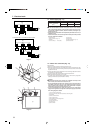
2) Connecting procedures (Fig. 7-7)
1 Connect the remote controller cord to the terminal block.
A To the terminal block on the indoor unit
B TB6 (No polarity)
2 Set the dip switch No.1 shown below when using two remote controller’s for the
same group.
C Dip switches
Setting the dip switches
The dip switches are at the bottom of the remote controller. Remote controller Main/
Sub and other function settings are performed using these switches. Ordinarily, only
change the Main/Sub setting of SW No.1. (The factory settings are all “ON”.)
30
46
30
30120
83.5
A
B
C
F
A
H
C
D
E
G
I
I
I
H
B
J
H
B-1. B-2.
Fig. 7-6
A
AB TB6
B
1
234
ON
1
234
ON
C
<SW No. 1>
SW contents Main Remote controller Main/Sub setting
ON/OFF
Comment Set one of the two remote controllers at one group to “Main”
Main/Sub
<SW No. 2>
SW contents Main When remote controller power turned on
ON/OFF
Comment
When you want to return to the timer mode when the power is restored
after a power failure when a Program timer is connected, select “Timer
mode”.
Normally on/Timer mode on
<SW No. 3>
SW contents Main Cooling/heating display in AUTO mode
ON/OFF
Comment
When you do not want to display “Cooling” and “Heating” in the Auto
mode, set to “No”.
Yes/No
<SW No. 4>
SW contents Main Intake temperature display
ON/OFF
Comment When you do not want to display the intake temperature, set to “No”.
Yes/No
Fig. 7-5
Fig. 7-7
LN
N
3
N
2 3
1
2
5
LN
2
5
12
7
6
3
4
(1) SEZ-A12AR (1:1 SYSTEM) (2) SEZ-A18/24AR (1:1 SYSTEM) OR
MULTI SYSTEM