


8
7. Electrical work
N
A
B
H
C
F
D
E
A
G
N
2
3
N
2
3
N
L
L
1 2
N
B
C
F
E
N
2
3
12
N
L
L
A
H
A
D
C
E
A
G
N
3
N
F
N
L
L
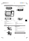
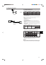
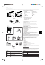
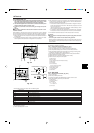
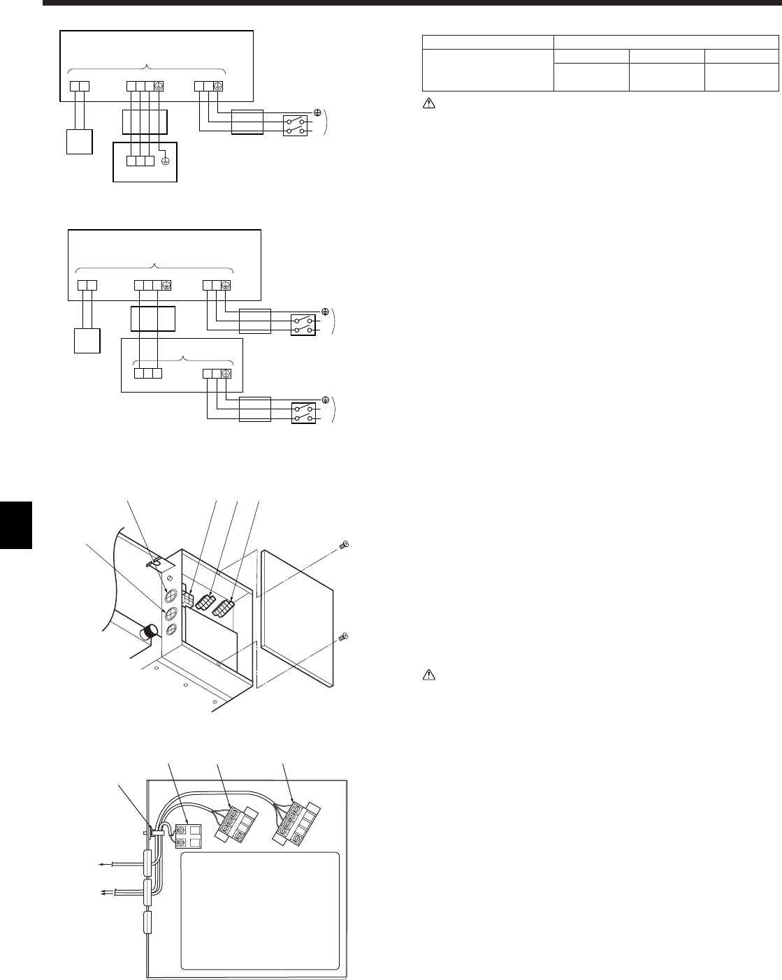
(1) SEZ-A12AR (1:1 SYSTEM)
7.1. Power supply (Fig. 7-1)
Electrical specification Input capacity Main Switch/Fuse (A)
Power supply SEZ-A12AR SEZ-A18AR SEZ-A24AR
(1 phase ~/N, 220-240V,
50Hz)
10 20 20
Warning:
• Do not use intermediate connection of the power cord, etc. or an extension
cord or connect many devices to one AC outlet. It could cause a fire or elec-
tric shock due to defective contact, defective insulation, exceeding the per-
missible current, etc.
• Supply power should be taken from independently branched circuit. If not, it
could cause a fire.
• A switch with at least 3 mm contact separation in each pole shall be provided
by the air conditioner installation.
A Terminal block
B Indoor unit (Refer to Fig. 7-2)
C Breaker
D 4-core cable ((2) · · · 2-core cable)
E 3-core cable
F Power supply
G Outdoor unit (Refer to Fig. 7-3)
H Remote controller
(2) SEZ-A18/A24AR (1:1 SYSTEM) OR MULTI SYSTEM
Fig. 7-1
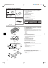
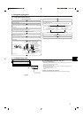
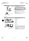
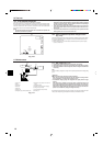
Fig. 7-2
7.2. Indoor wire connection (Fig. 7-2)
Work procedure
1.Remove 2 screws to detach the electric component cover.
2.Route each cable through the wiring intake into the electric component box. (Pro-
cure power cable and in-out connecting cable locally and use remote control cable
supplied with the unit.)
3.Securely connect the power cable and the in-out connecting cable and the remote
control cable to the terminal blocks.
4.Secure the cables with clamps inside the electric component box.
5.Attach the electric component cover as it was.
• Fix power supply cable and indoor/outdoor cable to control box by using buffer
bushing for tensile forse. (PG connection or the like.)
Warning:
• Attach the electrical part cover securely. If it is attached incorrectly, it could
result in a fire, electric shock due to dust, water, etc.
• Use the specified indoor/outdoor unit connecting wire to connect the indoor
and outdoor units and fix the wire to the terminal bed securely so that no
stress is applied to the connecting section of the terminal bed. Incomplete
connection or fixing of the wire could result in a fire.
• The wiring configuration of the indoor unit’s fan motor is for a 50Hz power
supply. The wiring must be reconfigured if a 60Hz power supply is used. Refer
to the wiring diagram for details.
1 Entry for remote controller cable
2 Entry for power supply cable and Indoor-Outdoor connecting cable
3 Cable clamp
4 Remote controller terminal
5 Power supply terminal
6 Indoor/Outdoor unit connecting terminal
7 To remote controller
8 To power supply source
9 To outdoor unit
0 Indoor controller
2
1456
3
4
5
6
0
7
8
9