11
9. Air filter installation
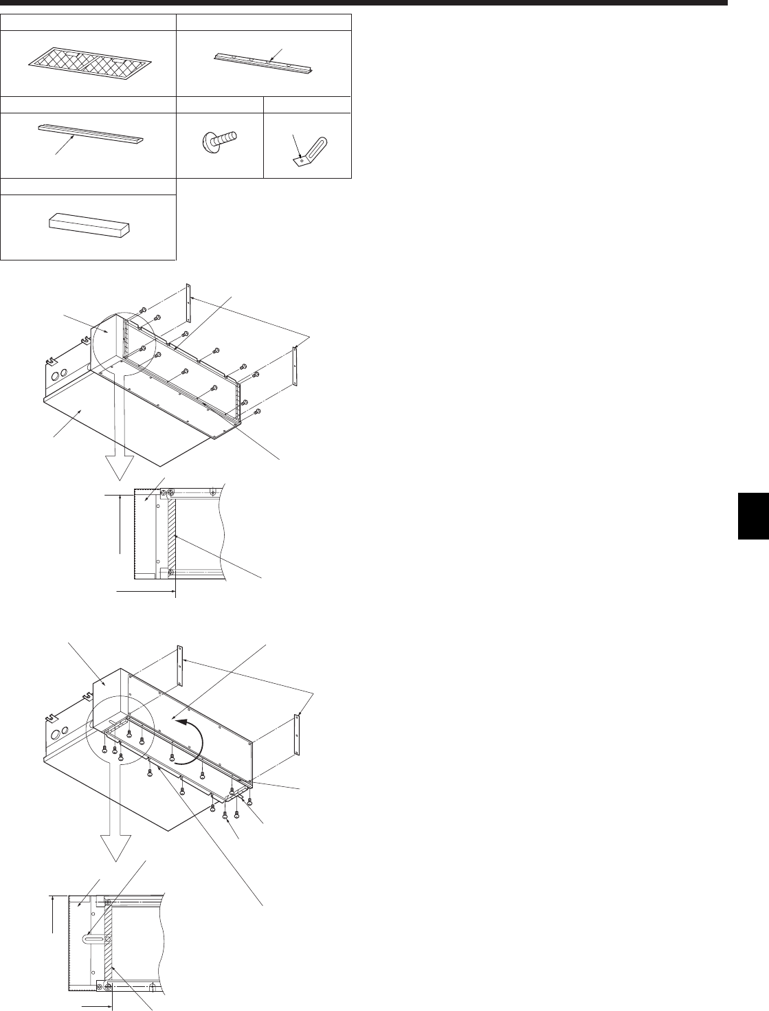
9.1. Confirmation of enclosed parts (Fig. 9-1)
• Please ensure all the parts shown below are present before starting installation.
1 Filter × 1
2 Filter rail × 1
3 Filter rail × 1
4 ST. screw (4 × 10) × 14
5 Clamp × 2
6 Seal × 2
12
3
Fig. 9-1
6
Cut out
Cut out
Hole
45
A
A
B
C
C
2
1
3
4
Fig. 9-2
9.2. Filter rail installation (Rear air intake) (Fig. 9-2)
■ Please select air intake direction A or B
1. Transportation support remove (Throw away).
2. Please attach filter rail 2 as per the diagram (screw × 6).
Please connect rails 2 3 carefully.
3. Please attach filter rail 3 as per the diagram (screw × 6).
Please connect rails 2 3 carefully.
4. Seal 6
Upright position here.
A Control box
B Drain pan
C Air tight seal
Level with edge
A
A
5
4
C
C
4
3
5
6
2
1
Fig. 9-3
9.3. Filter rail installation (Bottom air intake) (Fig. 9-3)
1. Transportation support remove (Throw away).
2. Please move the plate position. (Please use the screws removed.)
3. Please attach filter rail 2 as per the diagram (screw × 6).
Please connect rails 2 3 carefully.
4. Please attach filter rail 3 as per the diagram (screw × 6).
Please connect rails 2 3 carefully.
5. Clamp 5 (Attach the clamps 5 with screw × 2)
Upright position here.
6. Seal 6
Upright position here.
A Control box
C Air tight seal
Level with edge


