


[ II Restrictions ]
37- 37 -
HWE08040 GB
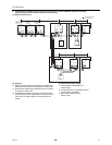
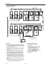
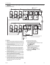
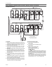
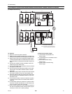
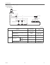
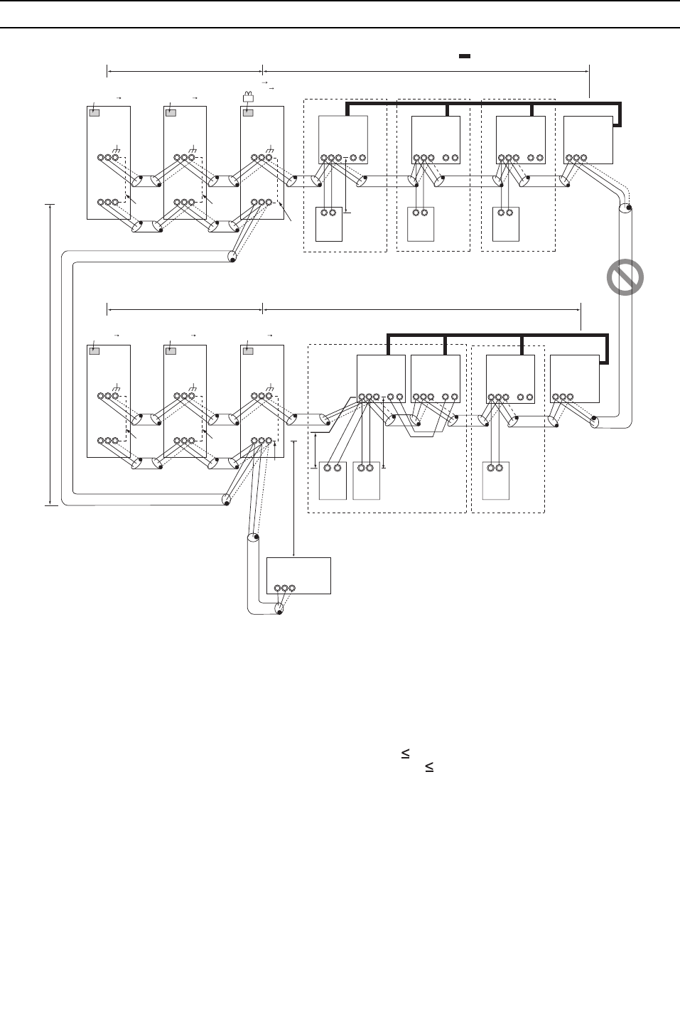
[6] An Example of a System to which an M-NET Remote Controller is connected
(1) Sample control wiring
(2) Cautions
1) M-NET remote controller and MA remote controller can-
not both be connected to the same group of indoor units.
2) No more than 3 M-NET remote controllers can be con-
nected to a group of indoor units.
3) Do not connect the terminal blocks (TB5) on the indoor
units that are connected to different outdoor units with
each other.
4) Replace the power jumper connector of the control board
from CN41 to CN40 on only one of the outdoor units.
5) Provide an electrical path to ground for the S terminal on
the terminal block for centralized control on only one of
the outdoor units.
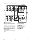
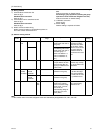
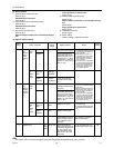
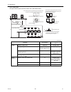
6) A transmission booster must be connected to a system
in which the total number of connected indoor units ex-
ceeds 20.
7) A transmission booster is required in a system to which
more than 16 indoor including one or more indoor units
of the 72 model or above are connected.
8) When a power supply unit is connected to the transmis-
sion line for centralized control, leave the power jumper
connector on CN41 as it is (factory setting).
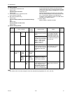
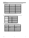
(3) Maximum allowable length
1) Indoor/outdoor transmission line
Same as [5] 3.
2) Transmission line for centralized control
Same as [5] 4.
3) M-NET remote controller wiring
Maximum overall line length
(0.3 to 1.25mm
2
[AWG22 to 16])
m1 10m [32ft]
m2+m3 10m [32ft]
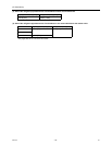
If the standard-supplied cable must be extended, use a
cable with a diameter of 1.25mm
2
[AWG16]. The section
of the cable that exceeds 10m [32ft] must be included in
the maximum indoor-outdoor transmission line distance
described in (1).
When connected to the terminal block on the Simple re-
mote controller, use cables that meet the following cable
size specifications: 0.75 - 1.25 mm
2
[AWG18-14].
IC
TB5
S
TB
15
1 2
01
IC
TB5
S
TB
15
1 2
02
LC
TB5
S
07
IC
TB5
S
1 2
TB
15
IC
TB5
S
TB
15
1 2
0504
LC
TB5
S
08
IC
TB5
S
TB
15
1 2
03
IC
TB5
S
TB
15
1 2
06
A B
RC
101
A B
RC
102
A B
RC
103
Group
Group
GroupGroupGroup
M1 M2 M1 M2 M1 M2 M1 M2
M1 M2 M1 M2 M1 M2 M1 M2
L12L11
L22L21
L31
A B S
L32
Note1
System controller
Interlock operation with
the ventilation unit
OC
TB3
TB7
S
51
m1
OS1
TB3
TB7
S
52
OS2
TB3
TB7
M1 M2 M1 M2 M1 M2
M1 M2 M1 M2 M1 M2
S
53
OC
TB3
TB7
S
54
OS1
TB3
TB7
S
55
OS2
TB3
TB7
M1 M2 M1 M2 M1 M2
M1 M2 M1 M2 M1 M2
S
56
Leave the male
connector on
CN41 as it is.
SW2-1 OFF ON
Leave the male
connector on
CN41 as it is.
SW2-1 OFF ON
Leave the male
connector on
CN41 as it is.
SW2-1 OFF ON
Leave the male
connector on
CN41 as it is.
SW2-1 OFF ON
Leave the male
connector on
CN41 as it is.
SW2-1 OFF ON
SW2-1 OFF ON
CN41 CN40 Replace
Connect
Not
connect
Not
connect
Not
connect
104
A B
RC
154
A B
RC
m3
106
A B
RC
m2
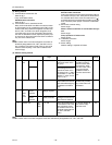
Note1 When only the LM adapter is connected,
leave SW2-1 to OFF (as it is).
Note2 LM adapters require the power supply
capacity of single-phase AC 208/230V.
Not
connect
Not
connect