


34
11
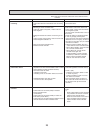
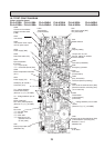
DISASSEMBLY PROCEDURE
OPERATING PROCEDURE
PHOTOS & ILLUSTRATIONS
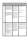
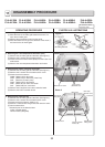
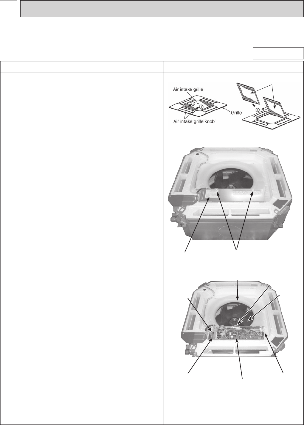
1. Removing the air intake grille
(1) Slide the knob of air intake grille toward the arrow to
open the air intake grille.
(2) Remove drop prevention hook from the panel.
(3) Slide the shaft in the hinge to the direction of the arrow
and remove the air intake grille.
Be careful on remov-
ing heavy parts.
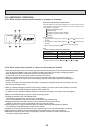
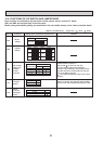
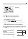
PLA-A12BA PLA-A18BA PLA-A24BA PLA-A30BA PLA-A36BA PLA-A42BA
PLA-A12BA
1 PLA-A18BA1 PLA-A24BA1 PLA-A30BA1 PLA-A36BA1 PLA-A42BA1
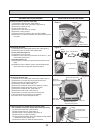
2. Removing the room temperature thermistor (TH1)
(1) Remove the air intake grille and the filter. (See Figure 1)
(2) Remove the 2 screws from the electrical box.
(3) Disconnect the connector CN20 (Red) from the indoor con-
troller board.
(4) Remove the room temperature thermistor and holder.
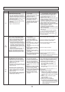
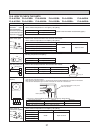
3. Removing the indoor controller board (I.B)
(1) Remove the air intake grille and the filter. (See Figure 1)
(2) Remove the 2 screws from the electrical box cover.
(3) Disconnect the connectors :
CNMF (White/ 7P) for fan motor
CN44 (White/ 4P) for thermistor (TH2/ TH5)
CNP (Blue/ 3P) for drain pump
CN4F (White/ 4P) for float switch
CN01 (Black/ 5P) for earth and reactor
CNV (White/ 20P) for vane motor
(4) Remove the 6 supports from indoor controller board.
(5) Remove the indoor controller board.
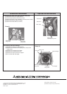
4. Removing the electrical box
(1) Remove the air intake grille and the filter. (See Figure 1)
(2) Remove the 2 screws from the electrical box cover.
(3) Disconnect the connectors. (Refer to 3.)
(4)
Remove 2 electrical box fixing screws and remove 2 hooks.
(5) Pull the electrical box.
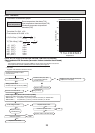
<Electrical parts in the electrical box>
Indoor controller board
Terminal block (TB4)(TB5)
Filter
Photo 1
Electrical box cover
Fixing screw
(Electrical box)
Photo 2
Electrical box
Electrical box
Fixing screw
Indoor controller
board (I.B)
Electrical box
Fixing screw
Bell mouth
Room temp.
thermistor (TH1)
Turbo fan
Figure 1