


18
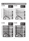
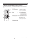
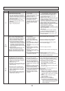
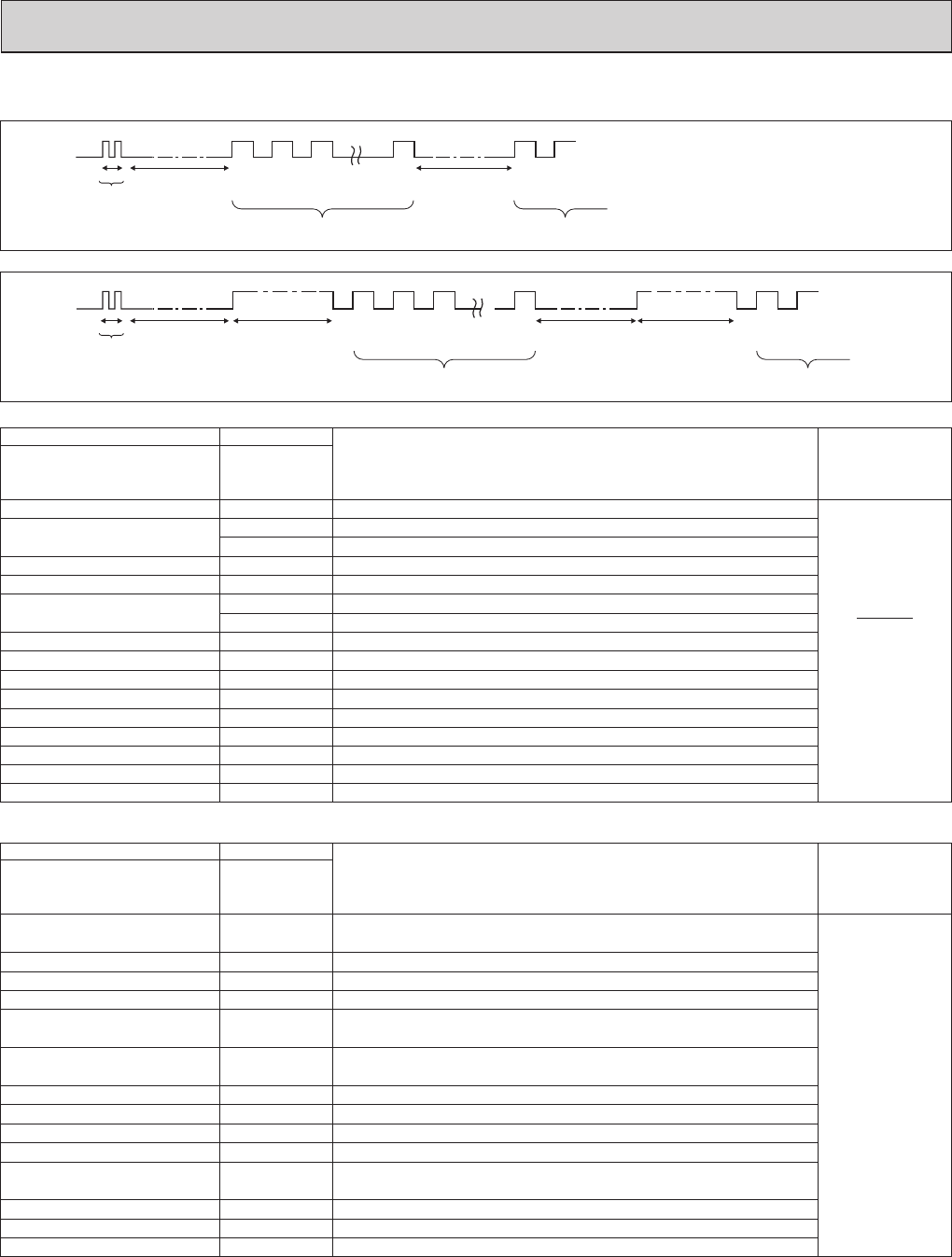
[Output pattern A] Errors detected by indoor unit
[Output pattern B]
E9
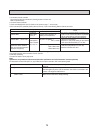
*1If the beeper does not sound again after the initial
2 beeps to confirm the self-check start signal was received and
the OPERATION INDICATOR lamp does not come on,
there are no error records.
*2If the beeper sounds 3 times continuously “beep, beep, beep (0.4 + 0.4 + 0.4 sec.)” after the initial 2 beeps to confirm
the self-check start signal was received, the specified refrigerant address is incorrect.
OPERATION
INDICATOR
lamp blink
pattern
Beep Beep Beep Beep Beep
Beep Beep
Off
Approx. 2.5 sec.
On
Approx. 3 sec.
On
0.5 sec.
On
0.5 sec.
On
0.5 sec.
On
0.5 sec.
Off
Approx. 2.5 sec.
On
Approx. 3 sec.
On
0.5 sec.
On
0.5 sec.
· · · Repeated
Number of blinks/beeps in pattern indicates the check
code in the following table (i.e., n=5 for “U2”)
Number of blinks/beeps in pattern indicates
the check code in the following table
n
th
1
st
2
nd
3
rd
1
st
2
nd
Self-check
starts
(Start signal
received)
Beeper sounds
[Output pattern B]
OPERATION
INDICATOR
lamp blink
pattern
Beep
Beep Beep Beep Beep Beep Beep
Off
Approx. 2.5 sec.
On
0.5 sec.
On
0.5 sec.
On
0.5 sec.
On
0.5 sec.
Off
Approx. 2.5 sec.
On
0.5 sec.
On
0.5 sec.
· · · Repeated
Number of blinks/beeps in pattern indicates the check
code in the following table (i.e., n=5 for “P5”)
Number of blinks/beeps in pattern indicates
the check code in the following table
n
th
1
st
2
nd
3
rd
1
st
2
nd
Self-check
starts
(Start signal
received)
Beeper sounds
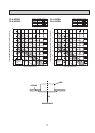
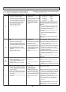
• Refer to the following tables for details on the check codes.
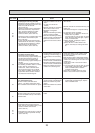
[Output pattern A]
Beeper sounds/OPERATION
INDICATOR lamp blinks Check code
Symptom Remark
(Number of times)
Wireless remote controller
Wired remote controller
Beeper sounds/OPERATION
INDICATOR lamp blinks Check code
(Number of times)
Wireless remote controller
Wired remote controller
1P1
Intake sensor error
P9 Pipe (TH5) sensor error
2
P2 Pipe (TH2) sensor error
3 E6,E7
Indoor/outdoor unit communication error
4 P4 Float switch connector open
5
P5
PA
Drain pump error
Forced compressor stop(due to water leakage abnormality)
6 P6 Freezing/Overheating protection operation
7 EE Communication error between indoor and outdoor units
8 P8 Pipe temperature error
9 E4, E5 Remote controller signal receiving error
10
–
11
–
–
–
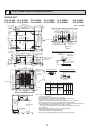
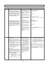
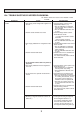
Errors detected by unit other than indoor unit (outdoor unit, etc.)
Symptom Remark
1
Indoor/outdoor unit communication error
2
(Transmitting error) (Outdoor unit)
3
Open/short of outdoor unit thermistors
4
Compressor overcurrent interruption (When compressor locked)
5
Abnormal high discharging temperature/49C worked/
insufficient refrigerant
6
Abnormal high pressure (63H worked)/Overheating
protection operation
7
Abnormal temperature of heatsink
8
Outdoor unit fan protection stop
9
Compressor overcurrent interruption/Abnormal of power module
10
Abnormality of superheat due to low discharge temperature
11
Abnormality such as overvoltage or voltage shortage and
abnormal synchronous signal to main circuit/Current sensor error
12
13
U2
U5
UP
U3,U4
UF
U1,Ud
U8
U6
U7
U9,UH
Others
–
–
–
–
14
Other errors (Refer to the technical manual for the outdoor unit.)
For details, check
the LED display
of the outdoor
controller board.
As for outdoor
unit, refer to
outdoor unit's
service manual.
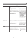
12 Fb Indoor unit control system error (memory error, etc.)
–
E0, E3
– E1, E2 Remote controller control board error
Remote controller transmission error
Compressor overcurrent interruption