


12
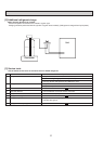
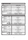
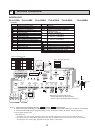
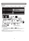
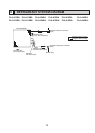
INDOOR UNIT
PLA-A12BA PLA-A18BA PLA-A24BA PLA-A30BA PLA-A36BA PLA-A42BA
PLA-A12BA
1 PLA-A18BA1 PLA-A24BA1 PLA-A30BA1 PLA-A36BA1 PLA-A42BA1
7
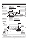
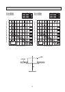
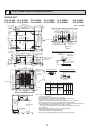
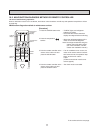
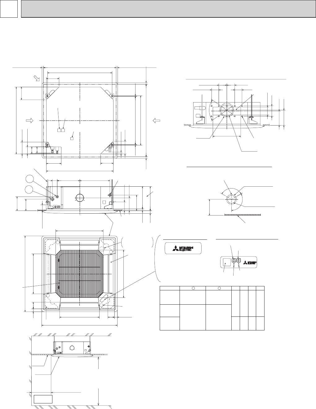
OUTLINES AND DIMENSIONS
Unit : inch(mm)
14-27/3211-3/16
2-3/8
+5
0
(7.5)
+35
-5
(160)
(500)
(950)
Floor
Min.94-1/2(2400)
from floor
Entire
periphery
(36)
(83)
(83)
(36)
(500)
(950)
(597)
(597)
( 158)
(
:
175)
(350)
(
:
150)
(
14-
:
2.8
)
(167)
(155)
(130)
(100)
(90)
(90)
(100)
(100)
(35)
(17 )
+3/16
0
(190)
(156)
(105)
(50~70)
(140)
(170)
(377)
(284)
(60)
(24)
(187.5)
(840)
(160)
(160)
(20~45)
to 1-25/32
(860~910)
(620)
(605 )
-3/16
+1-3/8
(90)
(150)
(160)
(7.5)
(20
~45)
1-25/32
Corner pocket
In case of wireless remote controller
In case of standard grille
Note1. As for drain pipe, please use VP-25(O.D.
:
1-1/4(
:
32) PVC TUBE).
Drain pump is included.
Max. liftng height is 70-7/18(850mm) from the ceiling.
2. As for suspension bolt, please use M10 or W3/8.(Procured at local site)
3. Electrical box may be removed for the service purpose.
Make sure to slack the electrical wire little bit for control/power wires connection.
4. The height of the indoor unit is able to be adjusted with the grille attached.
5. For the installation of the optional high efficiency filter or optional multi-functional casement.
1) Add 5-5/16(135mm)to the dimensions
+
marked on the figure.
2) The optional high efficiency filter becomes optional multi-functional casement and
concomitant use.
6. When installing the branch ducts, be sure to insulate adequately.
Otherwise condensation and dripping may occur.
(It becomes the cause of dew drops/water dew.)
7. As for necessary installation/service space, please refer to the left figure.
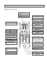
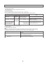
Drain hole
Drain pump clean hole
and Drain emergency
drainage hole
For MA-Remote controller
terminal block
Emergency operation switch<Cooling>
Emergency operation switch<Heating>
Indoor unit
Ceiling
Cut out hole
Burring hole pitch
3-
:
1/8(3-
:
2.8)
Burring hole
Detail drawing of fresh air intake hole
Burring hole
14-
:
1/8
Cut out hole
Burring hole pitch
Cut out hole
Detail connecting of Branch duct(Both aspects)
(77)
3-1/32
(85)
3-11/32
(298)
11-3/4
11-1/16
(281)
(74)(80)(258)(241)
2-29/32
3-5/32
10-3/16
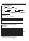
PLA-A36BA
PLA-A42BA
PLA-A24BA
PLA-A30BA
9-1/2
DCBA
2
Refrigerant pipe
····
:
15.88
Flared connection
····5/8 inch
Refrigerant pipe
····
:
12.7
Flared connection
····1/2 inch
1
Refrigerant pipe
····
:
6.35
Flared connection
····1/4 inch
Refrigerant pipe
····
:
9.52
Flared connection
····3/8 inch
Models
PLA-A12BA
PLA-A18BA
Min.19-11/16(500)
Grille
Ceiling
Suspension bolt
lower edge
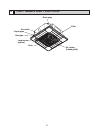
Vane motor
Air intake grille
Air outlet hole
Air outlet hole
Auto vane
(Air outlet)
Air intake hole
Air intake hole
Grille
Ceiling
Keep 25/64(10)to 19/32(15)
between unit ceiling
and ceiling slab.
)(
Connected the attached
flexible pipe or socket.
Drain pipe
connected to VP-25
Suspension bolt
M10 or W3/8
Branch duct hole
Fresh air
intake hole
Branch duct hole
Ceiling hole
Suspension bolt pitch
Suspension bolt pitch
Ceiling hole
(5/16)(5/16)
23-13/16
24-13/32
DEFROST/STAND BY lamp
Receiver
Operation lamp
For wiring replacement kit
terminal block
6-5/16
6-5/16
1
2
3-15/16
5-1/8
13-25/32
3-17/32
3-15/16
3-15/16
3-17/32
70˚
6-9/16
6-3/32
:
5-29/32
:
6-7/8
19-11/16
19-11/16
23-1/2
M
M
M
M
3-17/64
1-27/64
37-3/8
3-17/64
1-27/64
37-3/8
23-1/2
1-15/16~2-3/4
5-1/2
6-11/16
1-3/8
11/16
4-1/8
6-9/64
7-15/32
A
B
6-5/16
33-1/16(840)
5-29/32
3-17/32
C
D
33-1/16
7-3/8
25/32 to 1-25/32(20~45)
25/32 to 1-25/32(20~45)
33-27/32 to 35-13/16(860~910)
31-7/8(810)
25/32 to
33-27/32 to 35-13/1625/32
15/16
6-5/16
Indoor unit/Outdoor unit
connecting terminal block
:
4-29/32(
:
125)
:
3-15/16(
:
100)
6-7/32
120°
120°
++
+
++
+
+
+
+
+