


65
OPERATING PROCEDURE PHOTOS&ILLUSTRATION
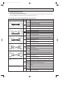
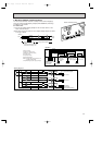
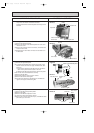
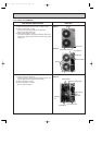
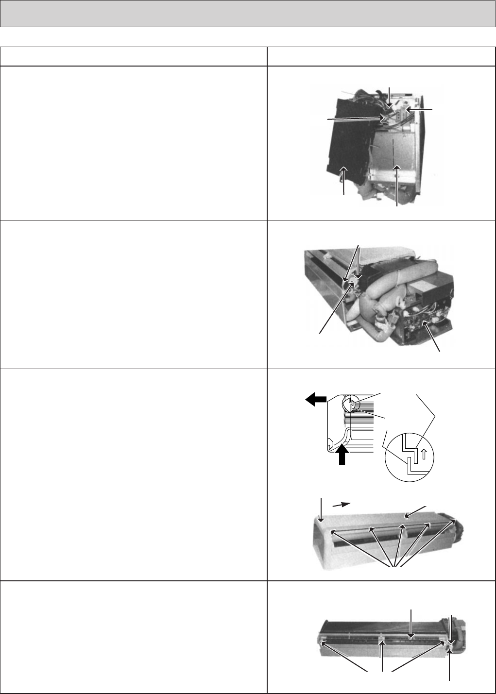
(8) Remove the screws of the indoor controller board case,
and pull out the indoor controller board case.
Then the transformer and the capacitor and relay can be
serviced.
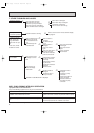
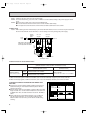
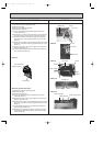
5. Removing the vane motor
(1) Remove the right side panel.
(2) Remove the screw of the electrical parts box cover, and
remove the cover.
(3) Remove the 2 screws of the vane motor, and remove the
motor from the shaft.
(4) Disconnect the vane motor connector on the indoor con-
troller board.
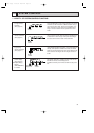
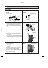
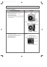
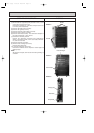
6 Removing the intake grills
(1) Remove the right side panel.
(2) To remove the left side panel, remove the screw on the
bottom and the screw on the upper left-hand side. (See
Figure 3.)
1. Press up this side of the left side panel to unhook the
catch on the panel from the catch on the unit.
2. Slide the left side panel to the left to remove the panel.
Note: Fix the unit to the metal fixture securely
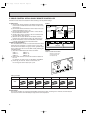
(3) Remove the air filters.
(4) Hold and press the center cover to remove.
(5) Remove the screws of the grills.
(6) Pull the lower side of the grill toward you and slide the
upper to the right to remove the grills.
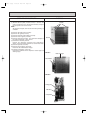
7. Removing the drain pan
(1) Remove the left and right side panels.
(2) Remove the grills.
(3) Remove the electrical parts box cover.
(4) Loosen the drain hose band to remove.
(5) Remove the 3 screws of the drain pan, and slide the drain
pan toward you to remove.
Screws
Drain pan
Drain hose
band
Drain hose
Photo 6
Photo 5
Figure 3
Screws for grills
Slide to the
right
Grills
Left side panel
Screws
Vane motor
Indoor controller board
Relay
Photo 4
Photo 3
Transformer
Capacitor
Electrical parts box
Indoor controller
board case
Catch on the left side panel
Catch on
the unit
OC120--3.qxp 24/6/97 12:56 AM Page 65