


64
11
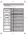
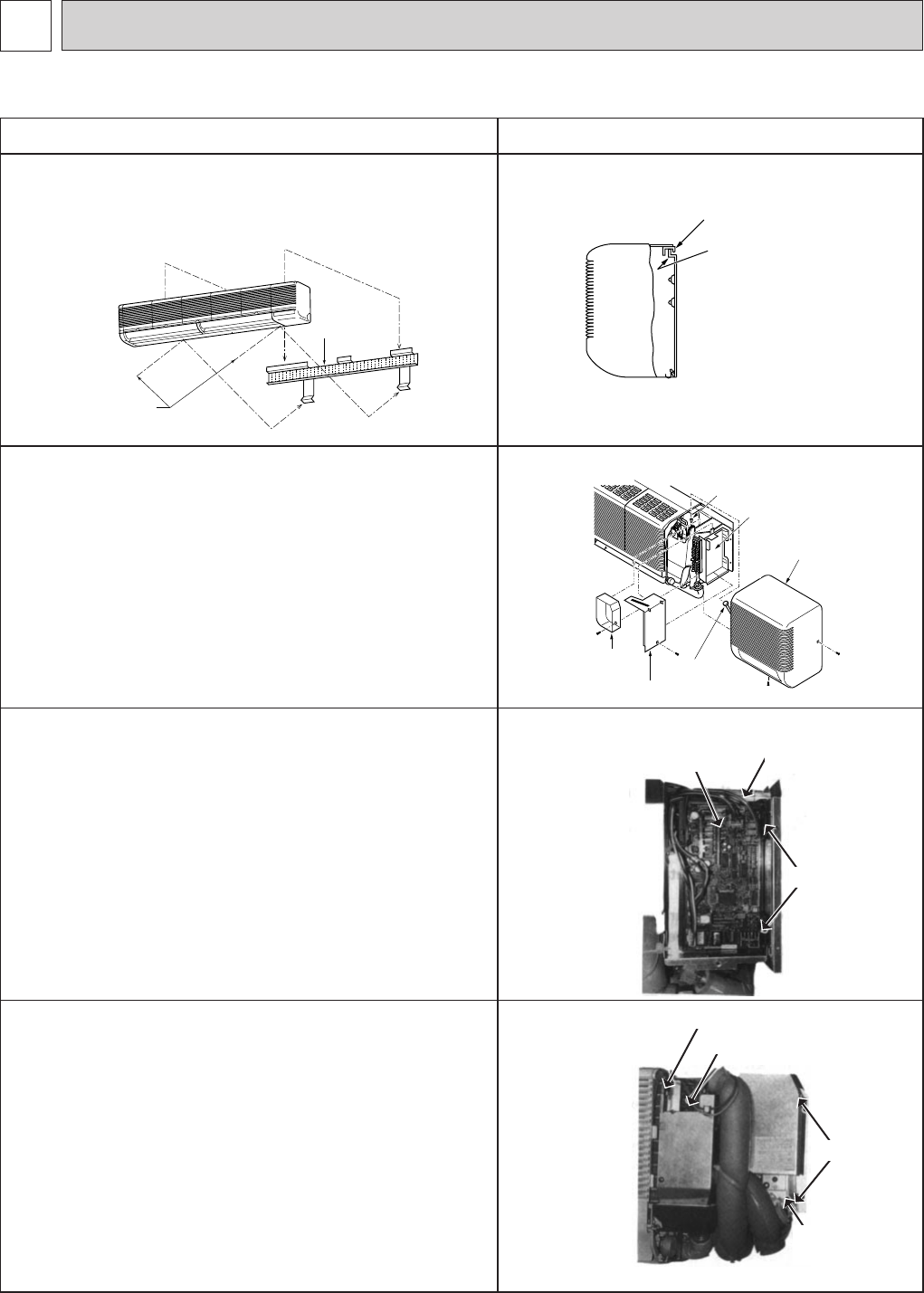
DISASSEMBLY INSTRUCTIONS
OPERATING PROCEDURE PHOTOS&ILLUSTRATION
Metal fixture
Screws
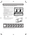
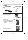
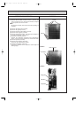
1. Removing the lower side of the indoor unit from the instal-
lation plate
(1) Remove the 2 screws.
Hang the indoor unit hangers to the catches on the instal-
lation plate.
Hanger of indoor unit
Catch of installation plate
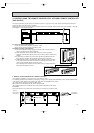
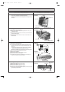
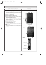
2. Removing the right side panel
(1) Remove the 2 screws of the right side panel:one on the
bottom and the other on the upper right-hand side.
(2) Disconnect the connector from the adapter case.
(3) Sliding the right side panel to the right, pull it out toward
you.
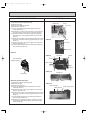
Terminal cover
Electrical parts box cover
Connector
Connector
Indoor controller
board
Right side panel
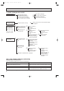
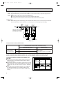
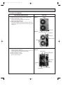
3. Removing the indoor controller board
(1) Remove the right side panel.
(2) Remove the screw of the electrical parts box cover, and
remove the cover.
(3) Disconnect the connectors on the indoor controller board.
(4) To unhook the catches on the right-hand side of the indoor
controller board, pull the left-hand side toward you and lift
up the cover to the right. Then the indoor controller board
can be removed.
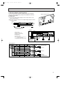
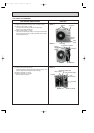
4. Removing the ielectrical parts box
(1) Remove the right side panel.
(2) Remove the screw of the electrical parts box cover, and
remove the cover.
(3) Remove the room temperature thermistor and the indoor
coil thermistor.
(4) Disconnect the vane motor connector on the indoor con-
troller board.
(5) Remove the 2 screws of the electrical parts box.
(6) Disconnect the connector of the heater lead wire connec-
tor.
(7) Disconnect the connector of the fan motor lead wire.
(8) Remove the electrical parts box.
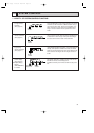
Figure 1
Figure 2
Photo 1
Photo 2
Indoor coil thermister
Catches
Screws
Room temperature thermister
Electrical parts
box
Electrical parts
box cover
Indoor controller
board
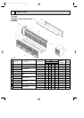
Indoor unit PKH24FK
OC120--2.qxp 24/6/97 12:33 AM Page 64