


- 93 -
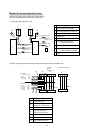
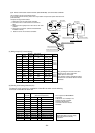
*1: This function can not use at above models, because the fan speed of these models is constant.
*2: If need this function, please consult your local MITSUBISHI ELECTRIC SALES office for application advice on this function.
*3: This function can change by customer self.
If this function use, The unit will auto start at power supply come back after power failure.
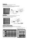
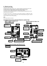
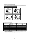
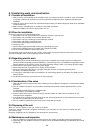
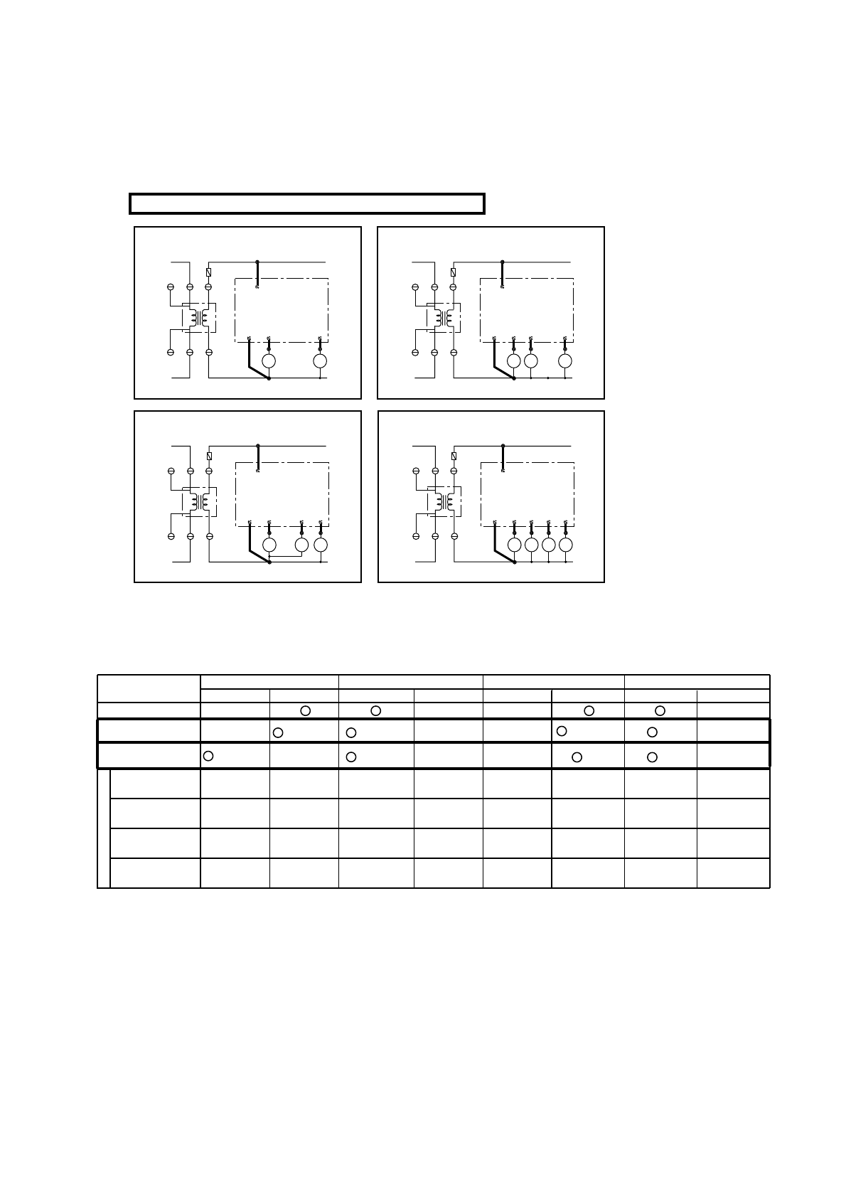
(3)-5. Setting DIP switch
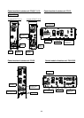
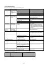
(3)-4. Wiring
Set the DIP switches on the basis of the below table.
TB4
CZ1
FZ
24VAC(N)
COMP1
FAN HI
TB4 1
F2
C04
(3.15A)
GRAY
GRAY
TB3
CZ
1-1
CZ
1-2
Tr
24VAC(L)
4
AC
24V
PE-7,8,10
23
TB3 1GRAY
GRAY
24VAC(N)
COMP1
24VAC(L)
COMP2
FAN HI
23 4
FZ
5
PE-15,20
Caution : This controller is damaged if mistook the connection.
Factory pre setting
PE setting
PEH setting
DIP Switch 1 DIP Switch 3 DIP Switch 4
Mode select Heat pump
DIP Switch 2
Fan speed
Hi / Lo (*1)
ON
Auto chang
over function (*2)
OFF
Auto start at
Power failure (*3)
Do not change DIP switch 2.
ON OFF ON OFF ON OFF
Cooling only
Available Not Available
Not Available Automatically
FUNCTION
(Not change)
(Change)
(Not change)
(Not change)
(Not change)
Note.
TB4
CZ1
FZ
24VAC(N)
COMP1
FAN HI
TB4 1GRAY
GRAY
TB3
CZ
1-1
CZ
1-2
24VAC(L)
5
PEH-5,7,8,10
24
HZ
4WV
3
TB3 1GRAY
GRAY
24VAC(N)
COMP1
24VAC(L)
COMP2
FAN HI
23 5
FZ
4WV
4
HZ1
6
PEH-15,20
PAC-204RC PAC-204RC
PAC-204RC PAC-204RC
(*2) (*3)
(*3)
1
C03
1
C03
1
C03
333
F2
C04
(3.15A)
Tr
AC
24V
1
C03
1
C03
1
C03
3
F2
C04
(3.15A)
Tr
AC
24V
1
C03
1
C03
1
C03
3
F2
C04
(3.15A)
Tr
AC
24V
1
C03
1
C03
1
C03
3
3
3
3
3
3
3
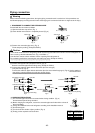
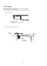
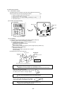
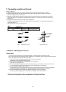
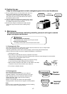
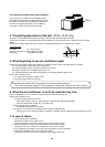
(1) Connect the wires on the basis of the following wiring diagram.
(2) Connecting work is different each models.
(3) LCD remote controller cables must be installed away from the power cables so that they are not influenced by electrical noise
from the power cables. (Do not place the LCD remote controller cables and power cables in the same conduit.)