


- 61 -
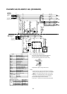
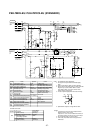
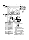
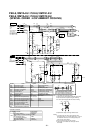
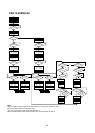
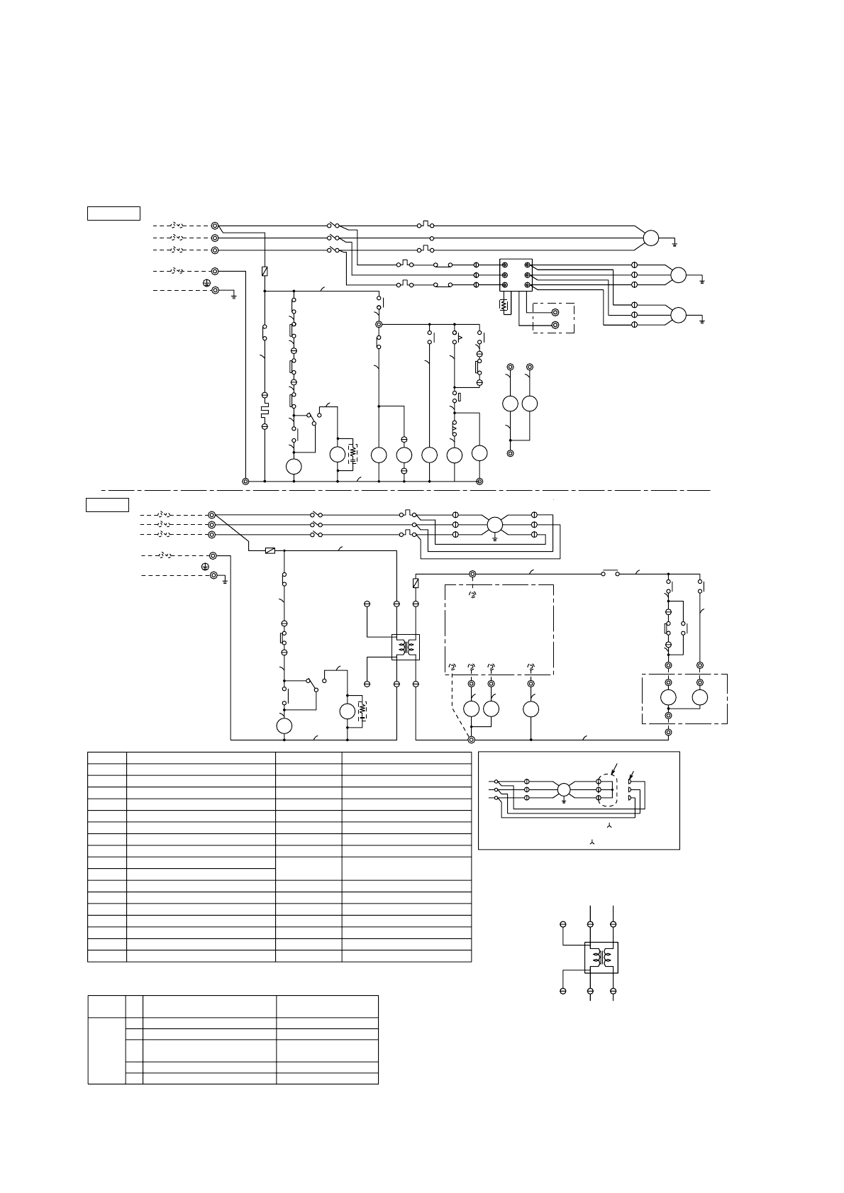
PEH-8,10MYA-EU / PUH-8,10MYE1-EU
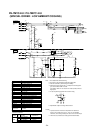
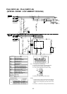
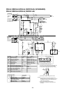
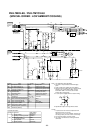
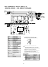
PEH-8,10MYA-EU / PUH-8,10MYC2-EU
(SPECIAL ORDER : LOW AMBIENT COOLING)
N
T2
T2
FC
TB6
2
1
C18
63H2
POWER SUPPLY
380~415VAC
3N~PE
50Hz
INDOOR
POWER SUPPLY
380~415VAC
3N~PE
50Hz
OUTDOOR
52F
MF1
51F1
L3
L2
L1
TB2
2
1
3
C01
PE
30
FZ
FZ
F1
PEH-8,10MYA-EU···15A
(3.15A)
CIRCUIT BREAKER
(FIELD SUPPLY)
(3.15A)
52F
52F
30FZ
51F1
F2
N
49F
C01
4
5
CR1
C02
X
Y
Z
1
3
2
U
V
W
333
C03
C03
1
RED
SILVER
C03
Tr
AC
24V
11
C04
HZ1
3
C16
1
26L
HZ1CZ1
14
13
15
15
HZ2
14
CZ2
TB3
13
NOTE 4
X1
X2
TB6
N
3
2
1
3
2
1
This circuit diagram shows connections.
(If the external static pressure is less
than 30 pa, change to connections.)
MF1
Attach the accessory
Remove
C01
3
1
2
C02
C21
MF3
3
2
1
L3
L2
L1
TB1
MF2
X1
51F2
1
2
3
51C
CIRCUIT BREAKER
(FIELD SUPPLY)
52C
MC
C11
PUH- 8MYC2-EU···50A
PUH-10MYC2-EU···60A
PUH- 8MYE1-EU···50A
PUH-10MYE1-EU···60A
PE
HZ2
51C
30
CZ
CZ2
51F2
63H1
14
CZ2
HZ2
15 13
N
52C
49C
30
CZ
52C
F3(3.15A)
CH
T1
X2
21
S4
X1
X1
T1
26D
CR2
C14
1
2
1
C13
3
1
C15
3
TB5
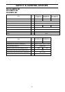
Controller connection.
4WVRevercing Valve
FAN HI
PAC-204RC
terminal no.
24VAC(N)
Symbol
TB4
No.
1
2
4
5
Function
Power (Active)
Cooling or Heating operation
Fan operation
Power (Neutral)
24VAC(L)
COMP1
3
for Heating operation
28
29
5
1
20
16
19
L1
N
15
18
13
6
17
25
L1
N
17
18
19
20
21
22
16
23
24
26
27
1315
14
BROWN
WHITE
BLUE
RED
RED
WHITE
BLUE
RED
WHITE
BLACK
RED
GRAY
BLUE
GRAY
RED
BLUE
PINK
PINK
PINK
GRAY
GRAY
GRAY
GRAY
BROWN
GRAY
BLACK
WHITE
RED
RED
BLUE
RED
WHITE
BLACK
RED
WHITE
BLACK
GRAY
RED
WHITE
BLACK
RED
WHITE
BLACK
RED
BLUE
BLUE
VIOLET
VIOLET
VIOLET
BROWN
BROWN
GRAY
VIOLET
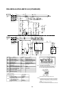
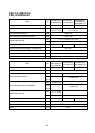
TimerT2
High-pressure switch (defrost)
63H2
Fan motor (outdoor)(*1)
Over current relay(fan O/D)51F2
13~16,18,21
Name
Symbol
52F
26L
High-pressure switch
63H1
Internal thermostat(indoor fan)
49F
Name
F1~3
51C
Tr
CH
51F1
52C
MF2,3
MF1
MC
TB1~6
Fan motor (indoor)
Fuse (3.15A)
Transformer
Crankcase heater
Contactor (fan I/D)
Over current relay(fan I/D)
Contactor (compressor)
Over current relay(compressor)
Terminal block
Symbol
Compressor motor
49C
Internal thermostat(compressor)
Thermostat(freeze protection)
Connector
Surge killerCR1,2
Contactor (fan O/D)
X2 Auxiliary relay (defrost)
T1 Timer
C01~04,11,
26D Thermostat (defrost)
FZ Auxiliary relay (fan)
Auxiliary relay (compressor)
Auxiliary relay (4-way valve)
Auxiliary relay (check)
X1
CZ1,2
HZ1,2
30CZ,30FZ
21S4 4-Way valve
OUTDOOR
(*1)
(*1)
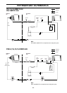
Note:1. The dotted lines show field wiring.
2. The figure in the parenthesis show field supply parts.
3. Color of earth wire is yellow and green twisting.
4. In case of power supply 380V AC model Tr wiring.
5. Specification subject to change without notice.
Caution,
1. To protect each fan motor and compressor from
abnormal current, over current relays<51C>,<51F1,2>
are installed. Therefore, do not change factory set
value of over current relays.
2. Do not change factory set value of timer.
3. This motor (*1) includes auto reset type internal
thermostat.
3
2
1
L1
L2
L3 W
V
U
C11
FC
N
LOW AMBIENT
COOLING PARTS
FULL LOAD INPUT
(ONLY HEAT PUMP)
TH
3
C03
SILVER
RED
1
C03
Tr
AC
24V
C03
1
C04
1
33
TB4
24VAC(N)
24VAC(L)
PAC-204RC
COMP1
4WV
FAN HI
HZ1
3
TB4
1
24
FZ
5
CZ1
2
3
4
GRAY GRAY GRAY