


- 50 -
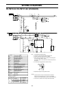
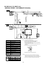
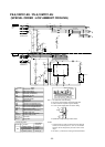
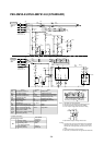
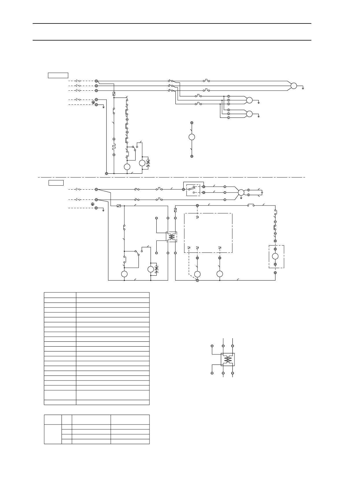
WIRING DIAGRAMS
INDOOR
OUTDOOR
POWER SUPPLY
220~240VAC
~PE
50Hz
POWER SUPPLY
50Hz
380~415VAC
3N~PE
33
C04
11
C03
SILVER
1
NOTE 5
RED
C03
AC
24V
Tr
3
C03
TB6
2
C14
1
3
C13
1
N
CR1
CR2
3
1
26L
CH
49C
52C
52C
F3(3.15A)
63H
51F2
CZ2
CZ
30
51C
CZ
30
TB4
24VAC(L)
PAC-204RC
24VAC(N)
COMP1
FAN HI
TB4
1
2
3
FZ
F2
CZ1
51F1
52F
(3.15A)
14
4
15
15
14
CZ2
TB3
CZ1
(3.15A)
F1
C16
30FZ
52F
FZ
FZ
30
15
TB5
CZ2
14
PU-7MYC1-EU···50A
PE-7MYC-EU···15A
PE
PE
24VAC(L)
Power (Neutral)
Fan operation
PAC-204RC
terminal no.
24VAC (N)
FAN HI
Cooling operation
Power (Active)
4
3
2
1
COMP1
Function
Controller connection.
No.
TB4
Symbol
MF1
C
5
6
Hi
Low
5
7
6
TB4
JUMPER
1
2
C01
C01
(*1)
SW2(FIELD SUPPLY)
4
52F
51F1
TB4
TB2
L
C21
C11
MC
3
2
1
MF3
52C
CIRCUIT BREAKER
(FIELD SUPPLY)
N
CIRCUIT BREAKER
(FIELD SUPPLY)
51C
3
2
1
51F2
MF2
TB1
L1
L2
L3
N
15
L
7
6
21
20
16
L1
8
4
3
2
1
L
19
18
17
22
21
20
19
18
17
16
14
15
N
N
PINK
PINK
RED
GRAY
RED
BLUE
GRAY
GRAY
GRAY
PINK
PINK
PINK
GRAY
VIOLET
VIOLET
VIOLET
VIOLET
GRAY
BLUE
RED
BLUE
RED
BLUE
BROWN
RED
BLACK
WHITE
RED
BLACK
WHITE
RED
GRAY
BLACK
WHITE
RED
BLACK
WHITE
RED
BLACK
RED
BLUE
WHITE
RED
GRAY
Fan motor (indoor)(*2)
Fan motor (outdoor)(*2)
Surge killer
CR1,2
Connector
C01,03,04,11,
13,14,16,21
Internal thermostat (compressor)
Run capacitorC
Compressor motor
Symbol
Terminal block
Over current relay (compressor)
Contactor (compressor)
Over current relay(fanI/D,O/D)
Contactor (fan I/D)
Crankcase heater
Transformer
Fuse (3.15A)
TB1~6
MC
MF1
MF2,3
52C
51F1,2
CH
Tr
51C
F1~3
Name
49C
63H
High-pressure switch
26L
Thermostat (compressor)
52F
SW1
FZ
Auxiliary relay (fan)
Auxiliary relay (compressor)
Auxiliary relay (check)
CZ1,2
30CZ,FZ
Switch (Fan Hi-Low)
(*2)
(*2)
(*2)
OUTDOOR
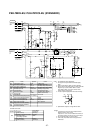
Note: 1. The dotted lines show field wiring.
2. The figure in the parenthesis show field supply parts.
3. Color of earth wire is yellow and green twisting.
4. Please remove the jumper wire ((*1) Mark) in the left diagram if
you use the switch <SW1> at local.
If the switch <SW1> is not used, the fan motor (indoor) drives at
high speed.
5. In case of power supply 220V AC model Tr wiring.
6. Specification subject to change without notice.
Caution,
1. To protect each fan motor and compressor from abnormal
current, over current relays <51C>, <51F1,2> are installed.
Therefore, do not change factory set value of over current relays.
2. This motor (*2) includes auto reset type internal thermostat.
3
C03
SILVER
RED
1
C03
Tr
AC
24V
C03
1
C04
1
33
PE-7MYC-EU /PU-7MYC1-EU (STANDARD)