


11
DFEINLPGRRU
CZSVHGPO
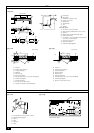
1. Insert the drain hose (accessory) into the drain port (insertion margin: 25 mm
[1 in.]).
(The drain hose must not be bent more than 45° to prevent the hose from
breaking or clogging.)
(Attach the hose with glue for the hard vinyl chloride pipe, and fix it with the
band (small, accessory).)
2. Attach the drain pipe (O.D. ø32 mm [1-1/4 in.] PVC TUBE, field supplied).
(Attach the pipe with glue for the hard vinyl chloride pipe, and attach it with the
band (small, accessory).)
3. Perform insulation work on the drain pipe (O.D. ø32 mm [1-1/4 in.] PVC TUBE)
and on the socket (including elbow).
4. Check the drainage. (Refer to [Fig. 7.3.1])
5. Attach the insulation (accessory), and attach it with the band (large, acces-
sory) to insulate the drain port.
[Fig. 7.2.2] (P.4)
A Indoor unit B Insulation (long) (accessory)
C Tie (long) (accessory) D Visible part
E Insertion margin F Drain hose (accessory)
G Drain pipe (O.D. ø32 mm [1-1/4 in.] PVC, field supplied)
H Insulation (field supplied) I Tie (short) (accessory)
J Max.180 ± 5 mm [7-3/32 ± 7/32 in.]
K The joint of the insulation must be positioned up.
[Fig. 7.2.3] (P.4)
A Indoor unit B Insulation (short) (accessory)
C Tie (short) (accessory) D Attaching the band
E Insertion margin F Drain hose (accessory)
G Drain pipe (O.D. ø32 mm [1-1/4 in.] PVC TUBE, field supplied)
H Insulation (field supplied)
I Max.145 ± 5 mm [5-23/32 ± 7/32 in.]
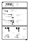
7.3. Confirming drain discharge
ss
ss
s Make sure that the drain-lift mechanism operates normally for discharge
and that there is no water leaking from the connections.
• Be sure to confirm the above when the system is operating in heating mode.
• Be sure to confirm the above before ceiling work is done in the case of a new
construction.
1. Remove the water supply port cover on the same side as the indoor unit pip-
ing.
2. Fill water into the feed water pump using a feed water tank. In filling, be sure to
put the end of the pump or tank in a drain pan. (If the insertion is incomplete,
water may flow over the machine.)
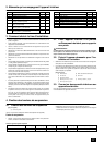
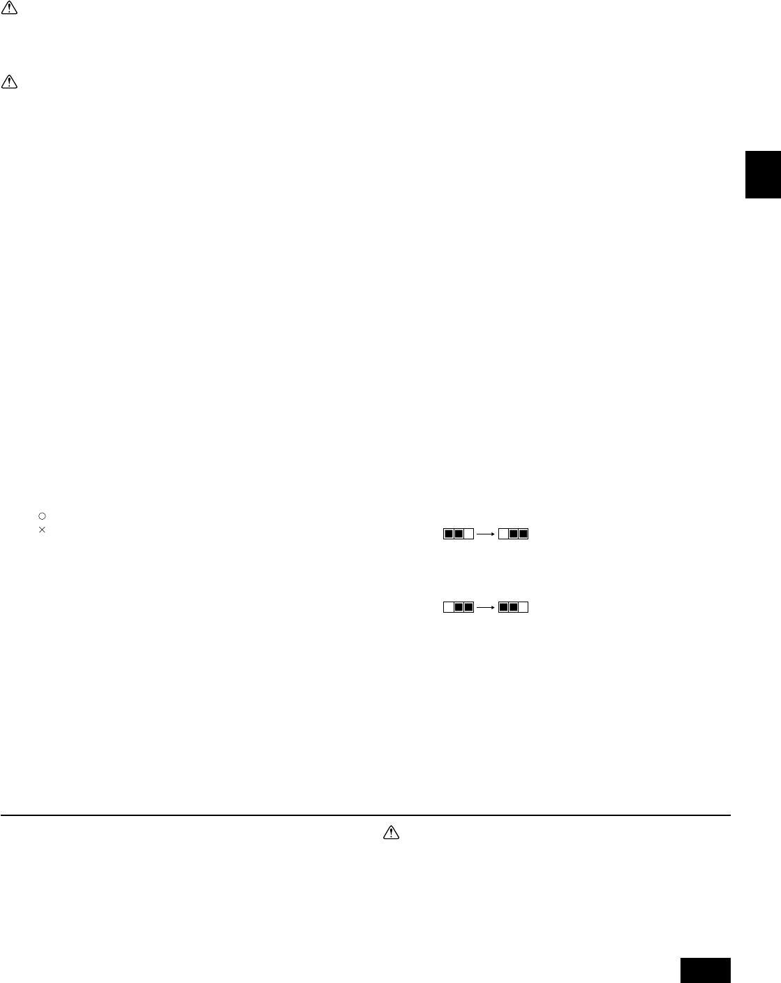
3. Perform the test run in cooling mode, or turn on the switch SWE on the control-
ler circuit board. (The drain pump and the fan are forced to operate without
remote controller operation.) Make sure using a transparent hose that drain is
discharged.
4. After confirmation, cancel the test run mode, and turn off the main power.
When
the switch SWE has been turned on, turn it off, and attach the water supply
port cover into its original position.
[Fig. 7.3.1] (P.4)
A Insert pump's end 2 to 4 cm [13/16 to 1-19/32 in.].
B Remove the water supply port.
C About 2 L
D Water
E Filling port
F Screw
[Fig. 7.3.2] (P.4)
<Indoor board>
Cautions on refrigerant piping
ss
ss
s Be sure to use non-oxidative brazing for brazing to ensure that no for-
eign matter or moisture enter into the pipe.
ss
ss
s Be sure to apply refrigerating machine oil over the flare connection sur-
face and tighten the connection using a double spanner.
ss
ss
s Provide a metal brace to support the refrigerant pipe so that no load is
imparted to the indoor unit pipe. This metal brace should be 50 cm [19-
11/16 in.] away from the indoor unit’s flare connection.
Warning:
When installing and moving the unit, do not charge it with refrigerant other
than the refrigerant specified on the unit.
- Mixing of a different refrigerant, air, etc. may cause the refrigerant cycle to mal-
function and result in severe damage.
Caution:
• Use refrigerant piping made of C1220 (Cu-DHP) phosphorus deoxidized
copper as specified in the JIS H3300 “Copper and copper alloy seamless
pipes and tubes.” In addition, be sure that the inside and outside sur-
faces of the pipes are clean and free of hazardous sulphur, oxides, dust/
dirt, shaving particles, oils, moisture, or any other contaminant.
•Never use existing refrigerant piping.
- The large amount of chlorine in conventional refrigerant and refrigerator oil
in the existing piping will cause the new refrigerant to deteriorate.
• Store the piping to be used indoors and keep both ends of the piping
sealed until just before brazing.
- If dust, dirt, or water get into the refrigerant cycle, the oil will deteriorate and
the compressor may fail.
•
Use ester oil, ether oil or alkylbenzene (small amount) as the refrigerator oil
to coat flares and flange connections. (For models using R410A)
- The refrigerant used in the unit is highly hygroscopic and mixes with water
and will degrade the refrigerator oil.
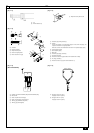
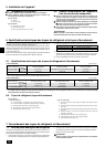
7.2. Drain piping work
• Ensure that the drain piping is sloping downward (pitch of more than 1/100) to
the outdoor (discharge) side. Do not install a trap.
• Ensure that any drain pipe length is less than 20 m [65 ft] (excluding the differ-
ence). If the drain piping is long, provide metal braces to prevent it from waving.
Never provide any air vent pipe. Otherwise drain may be ejected.
• Use a hard vinyl chloride pipe O.D. ø32 mm [1-1/4 in.] for drain piping.
• Ensure that collected pipes are 10 cm [3-15/16 in.] lower than the unit body’s
drain port.
• Do not provide any odor trap at the drain discharge port.
• Put the end of the drain piping at a location where no odor is generated.
•
Do not put the end of the drain piping in any drain where ionic gases are generated.
[Fig. 7.2.1] (P.4)
Correct piping
Wrong piping
A Insulation (9 mm [3/8 in.] or more)
B Decline (1/100 or more)
C Support metal
K Air release tube
L Tra p
M Odor trap
Drain pipe system
D O. D. ø32 mm [1-1/4 in.] PVC TUBE
E Make it as large as possible. About 10 cm [3-15/16 in.].
F Indoor unit
G Make the piping size large for drain pipe system.
H Decline (1/100 or more)
I O. D. ø38 mm [1-1/2 in.] PVC TUBE for drain pipe system.
(9 mm [3/8 in.] or more insulation)
J Up to 550 mm [21-21/32 in.]
N Drain hose (accessory)
O Horizontal or slightly upgradient
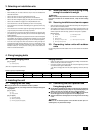
SWE SWE
OFF ON OFF ON
SWE SWE
OFF ON OFF ON
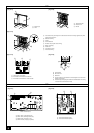
8. Duct work
• When connecting ducts, insert a canvas duct between the main body and the
duct.
• Use non-combustible duct components.
• Install sufficient insulation to prevent condensation forming on outlet duct flanges
and outlet ducts.
Caution:
•Keep the distance between the inlet grille and the fan over 850 mm
[33-15/32 in.].
If it is less than 850 mm [33-15/32 in.], install a safety guard on the fan.
[Fig. 8.0.1] (P.5)
A Air inlet B Air outlet
C Access door D Ceiling surface
E Canvas duct F Air filter