- 100 -
Method for connecting electric wire
Please do the wiring after consulting the electric power
company of jurisdiction beforehand in the instruction.
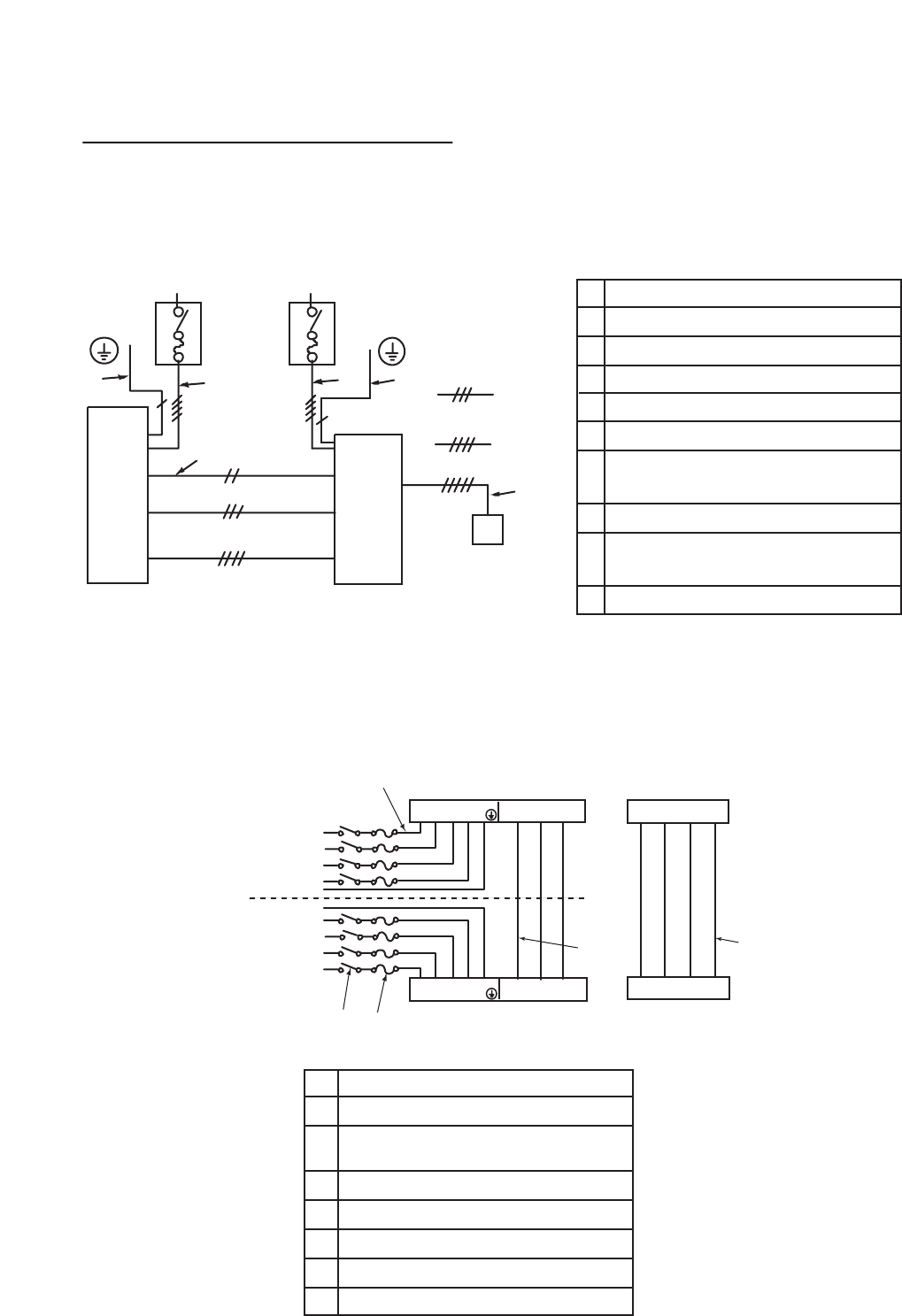
(1) The entire wiring diagram of unit.
a.
b.
c.
d.
e.
Power supply
Main switch/fuse (field supply)
Outdoor unit
(2) Power supply construction and electric wiring connection of indoor and outdoor unit.
f.
g.
Indoor unit
Connection wiring for indoor
/ outdoor units (polarity)
Power supply wiring for outdoor unit
A.
B.
C.
D.
Indoor unit
Power cable wiring
Control cable wiring
(Fixing wire-- Do not remove)
Outdoor unit
h.
i.
j.
Remote controller (field supply)
Connection wiring for indoor
/ remote controller (no polarity)
Earth
Power supply wiring for indoor unit
E.
F.
G.
H.
Breaker
Fuse
Power supply terminal bed
Control cable terminal bed
PE
PE
aa
b
b
e
f
h
g
c
d
j
j
i
In case of PE-7, 8, 10
In case of PE-15, 20
PEH-5, 7, 8, 10
In case of PEH-15,20
In case of PE-15,20
PEH-5, 7, 8, 10
In case of PEH-15, 20
In case of PE-7,8,10
L1 L2 L3 N
PE
14
15
L
1 L2 L3 N
PE
14 15
A 3phase
B
C
D
3 phase
EF
G
G
H
H
In case of PE(H)-15,20
11 12 13
H
In case of
PEH-5
PE(H)-7,8,10
11 12 13
C
H
13
13
PE(H)-7:Single phase
14
14
PEH only
PEH only
PEH-5 15A
PE(H)-7,8,10 15A
PE(H)-15,20 30A
PUH-5 50A
PU(H)-7,8 50A
PU(H)-10 60A
PU(H)-15 100A
PU(H)-20 125A


