


OC277-22
7
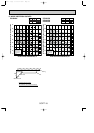
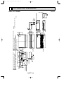
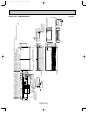
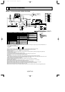
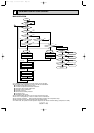
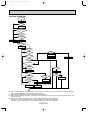
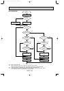
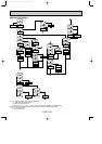
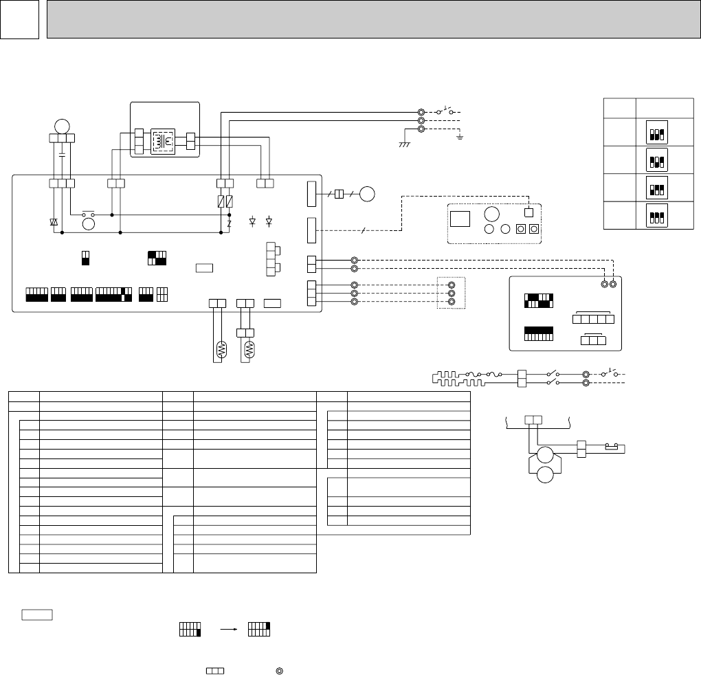
WIRING DIAGRAM
MODEL PCH24/30/36/42GK
WIRING DIAGRAM
TRANSMISSION WIRES
DC12V
ZNR
LED2LED1
F2 F1
RED
BLU
L2
L1
POWER SUPPLY
~(1PHASE)
AC208/230V 60Hz
TB2
WHT
BLK
POWER
CNDK
(WHT)
31
1
2
1
2
3
TRANS
CNSK
(RED)
(DC13.1V)
CN2S
(WHT)
P. B
(AC208/230V)
W.B
CN2
CN1
ON
OFF
ON
OFF
SW17
87654321
87654321
SW18
TRANSMISSION WIRES DC12V
123
54321
REMOCON
POWER
CN40
(WHT)
4
3
2
1
CENTRALLY
CONTROL
CN51
LOSSNAY
CN2L
TB5
BLU
BLU
1
2
REMOCON
CN22
(BLU)
SW9
12345
ON
OFFOFF
ON
12
SW3
2
1
SW7SW6SW2 SW5 SW8 SW1
1231234123456123456789101234123456
TB3
OUTDOOR UNIT
1
2
3
1
2
3
TB4
1
2
3
BRN
ORN
YLW
GRY
YLW
7
88H2
8
THERMAL FUSE<230°F/16A:30,36,42GK>
SWITCH(FUNCTION SELECTOR)
SW18
SWITCH(ADDRESS SELECTOR)
SW17
CONNECTOR(REMOTE SWITCH)
CN2
(32°F/15k",77°F/5.4k" DETECT)
SWITCH(MODEL SELECTOR)
SWITCH(OPTION)
SWITCH(MODEL SELECTOR)
SW7
SW8
SW9
SWITCH(MODEL SELECTOR)
SWITCH(EMERGENCY OPERATION)
SWITCH(ADDRESS SELECTOR)
SWITCH(FUNCTION SELECTOR)
SW2
SW1
123456
123
I.B
MF
C
RED
BLU
RED
WHT
BLK
WHT
BLK
FAN
(WHT)
135
OFF
POWER
CND
(RED)
FC
X4
X4
ON
TB6
B02A01
12
INTAKE
CN20
(RED)
OUT
DOOR
CN30
(BLU)
RT1 RT2
BLK
BLK
21
PIPE
CN21
(WHT)
21
RU
CNB
LED2
BZ
LED1 SW1SW2
R.B
9
VANE
CN6V
(WHT)
6
MV
CN2D
(WHT)
13 21
WIRELESS
CN90
(WHT)
6
GRN/YLW
88H2
88H1
BLU
53
RED
53
GR
L2
L1
H
RED
BLU
TB2
1
2
RED
WHT
FS1 FS2
POWER SUPPLY
~(1PHASE)
AC208/230V 60Hz
23
ON
1
OFF
23
ON
1
OFF
23
ON
1
OFF
23
ON
1
OFF
I.B
21
HEATER
CN24
(YLW)
YLW
YLW
78
88H1
GRY
6
5
26H
RED
RED
MODELS
SW7
LED(DC5V POWER)
LED2
VANE MOTORMV
LED(DC12V POWER)
VARISTOR
LED1
ZNR
SWITCH(COOLING ON/OFF)
SW2
SW1
LED2
RU
LED1
BZ
W.B
LED(RUN INDICATOR)
SWITCH(HEATING ON/OFF)
LED(HOT ADJUST)
BUZZER
RECEIVING UNIT
WIRELESS REMOTE CONTROLLER BOARD(OPTION)
THERMAL FUSE<243°F/16A:24GK>
TERMINAL BLOCK(REMOTE CONTROLLER
HEATER CONTACTOR
HEATER THERMAL SWITCH
HEATER
88H1,2
26H
FS1,2
TRANSMISSION LINE)
CONNECTOR(PROGRAM TIMER)
REMOTE CONTROLLER BOARD
TB6
CN1
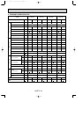
NAME
HEATER
R.B
TRANSMISSION LINE)
TERMINAL BLOCK(REMOTE CONTROLLER
TB5
P. B
PIPE TEMP.THERMISTOR/LIQUID
RT2
RT1 ROOM TEMP.THERMISTOR
(32°F/15k",77°F/5.4k" DETECT)
TERMINAL BLOCK(POWER)
TERMINAL BLOCK(INDOOR/OUTDOOR TRANSMISSION LINE)
TB4
TB2
FAN MOTORMF
CAPACITOR(FAN MOTOR)C
FUSE(6A/250V)
RELAY(FAN MOTOR)
SWITCH(TWIN/TRIPLE SELECTOR)
FAN PHASE CONTROL
CONNECTOR(CENTRALLY CONTROL)
CONNECTOR(LOSSNAY)
F1,F2
X4
SW6
SW5
SW3
FC
CN51
CN2L
INDOOR CONTROLLER BOARD
INDOOR POWER BOARD
I.B
NAME
SYMBOL
NAME
SYMBOLSYMBOL
H
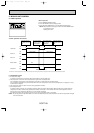
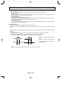
(1)Set the dip switch (SW3<I.B>) on the indoor controller board to 1 on and 2 off for cooling and 1 · 2 on for heating.
(2)Turn on outdoor unit side circuit breaker, then indoor unit side circuit breaker.
(3)During emergency operation, indoor fan runs at high speed but automatic vane does not work.
(4)Thermostat will not function. Cold air blows out for defrosting during heating thus do not operate defrosting for a long time.
(5)Emergency cooling should be limited to 10 hours maximum. (The indoor unit heat exchanger may freeze.)
(6)After every emergency operation, set all dip switch (SW3<I.B>) to OFF.
(7)Movement of the vane does not work in emergency operation, therefore you have to slowly set them manually to the appropriate position.
SW8
ON
OFF
123456
ON
OFF
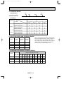
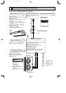
1.Since the indoor fan motor(MF)is connected with 230V power, using 208V power will require a setting change of the dip switch(SW8<I.B>) on
indoor controller board as shown in fig:*1.
NOTES:
Indoor fan motor(MF)for
208V.
fig:*1
2.Since the outdoor side electric wiring may change, be sure to check the outdoor unit electric wiring for servicing.
3.Indoor and outdoor connecting wires are made with polarities, make wiring matching terminal numbers.
4.Symbols used in wiring diagram above are, :Connector, :Terminal block.
5.Emergency operation
If remote controller or microcomputer fails but there is no other trouble, emergency operation is possible by setting dip switch (SW3<I.B>)
on the indoor controller board.
6.Fasten terminal of the terminal board "TB4" equips lock system.
To remove the fasten terminal, pull it while pressing the protruding portion (locking lever) of the terminal.
Connection of the fasten terminal, protruding portion should face upward.
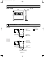
(1)Make sure that no other trouble exist in the outdoor unit. Trouble with the outdoor unit prevents emergency operation.
(If any trouble exists in the outdoor unit error code "P8" will be displayed on the remote controller and the trouble position will be shown on the
outdoor controller board LED. See electric wiring diagram of the outdoor unit for details.)
(2)Make sure that there is no trouble with the indoor fan.
Emergency operation will be continuous operation mode. (ON/OFF by the remote controller is not possible.)
[Check items]
[Emergency operation procedure]
24GK
30GK
36GK
42GK
OC277--1.qxp 01.12.14 13:02 Page 22