


7
A
Die
Copper pipe
Flare nut
Die
Copper pipe
Smooth all around
Even length
all around
Inside is shining without any scratches
York
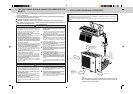
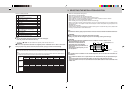
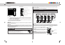
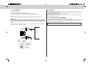
4. Flaring work
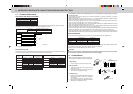
• Perform flaring work using flaring tool as shown in the right.
A (mm)
Outside diameter
Flare tool for R410A Conventional flare tool
clutch type Clutch type Wing nut type
ø6.35 mm 0 to 0.5 1.0 to 1.5 1.5 to 2.0
ø9.52 mm 0 to 0.5 1.0 to 1.5 1.5 to 2.0
ø12.7 mm 0 to 0.5 1.0 to 1.5 2.0 to 2.5
ø15.88 mm 0 to 0.5 1.0 to 1.5 —
Firmly hold copper pipe in a die in the dimension shown in the
table above.
5. Check
• Compare the flared work with the figure below.
• If flare is noted to be defective, cut off the flared section
and perform flaring work again.
5-3 PIPE CONNECTION
Note:
Fasten a flare nut with a torque wrench as specified in the table below.
When fastened too tight, a flare nut may be broken after a long period and cause a leakage of refriger-
ant.
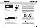
1. Indoor unit connection
• Connect both liquid pipe and gas pipe to indoor unit.
- Apply a thin coat of refrigeration oil to the seat surface of pipe.
- For connection, align the center of both pipe and union, then tighten the first 3 to 4 turns in flare nut by
hand.
- For tightening the union part of the indoor unit side, use the table below as a standard and tighten
the flare nut with two wrenches. Excessive tightening damages the flared section.
Pipe diameter
Tightening torque
N·m kgf·cm
ø6.35 mm 13.7 to 17.7 140 to 180
ø9.52 mm 34.3 to 41.2 350 to 420
ø12.7 mm 49.0 to 56.4 500 to 575
ø15.88 mm 73.5 to 78.4 750 to 800
2. Outdoor unit connection
• Connect pipes to the pipe joint part of the stop valve in the same method as the indoor unit.
- For tightening, use the same tightening torque applied for indoor unit and tighten the flare nut with
torque wrench or spanner.
INSULATION AND TAPING
1Cover piping joints with pipe cover.
2For outdoor unit side, surely insulate every piping including valves.
3Using piping tape E, apply taping starting from the entry of outdoor unit.
• Fix the end of piping tape E with adhesive tape.
• When piping has to be arranged through above ceiling, closet or area where the temperature and humidity
are high, wind additional commercially sold insulation for prevention of condensation.
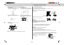
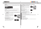
5-4 PURGING PROCEDURES • LEAK TEST
• Perform the manifold valve work securely according to the installation manual of the manifold valve.
Flaring tool
Wing nut type
Clutch type
PURGING PROCEDURES
Connect the refrigerant pipes (both liquid pipe and gas pipe) between the indoor and
the outdoor unit.
Remove the service port cap of the stop valve on the gas pipe side of the outdoor unit.
(The stop valve will not work in it initial state fresh out of the factory [totally closed with
cap on].)
Connect the gauge manifold valve and the vacuum pump to the service port of the stop
valve on the gas pipe side of the outdoor unit.
Run the vacuum pump. (Vacuumize for more than 15 minutes.)
Check the vacuum with the gauge manifold valve, then close the gauge manifold valve
and stop the vacuum pump.
Leave it as is for one or two minutes. Make sure the pointer of the gauge manifold
valve remains in the same position. Confirm that the pressure gauge shows –0.101
MPa [Gauge] (–760 mmHg).
Pipe length up to 40 m
No gas charge is needed.
Pipe length exceeding 40 m
Charge the prescribed
amount of gas. (refer to 5-1)
Remove the gauge manifold valve quickly from the service port of the stop valve.
After refrigerant pipes are connected and evacuated, fully open all stop valves on both
sides of gas pipe and liquid pipe.
Operating without fully opening lowers the performance and this causes trouble.
Tighten the cap to the service port to obtain the initial status.
Retighten the cap.
Leak test
(or the vacuum
pump with the
function to prevent
the back flow)
Gauge manifold
valve (for R410A)
Pressure gauge
(for R410A)
Compound pressure
gauge (for R410A)
-0.101MPa
(-760 mmHg)
Handle
Low
Handle High
Window
Charge hose (for R410A)
Vacuum
pump
Adapter for
preventing
the back flow
Charge hose
(for R410A)
Stop valve
(gas side)
Service port