


6
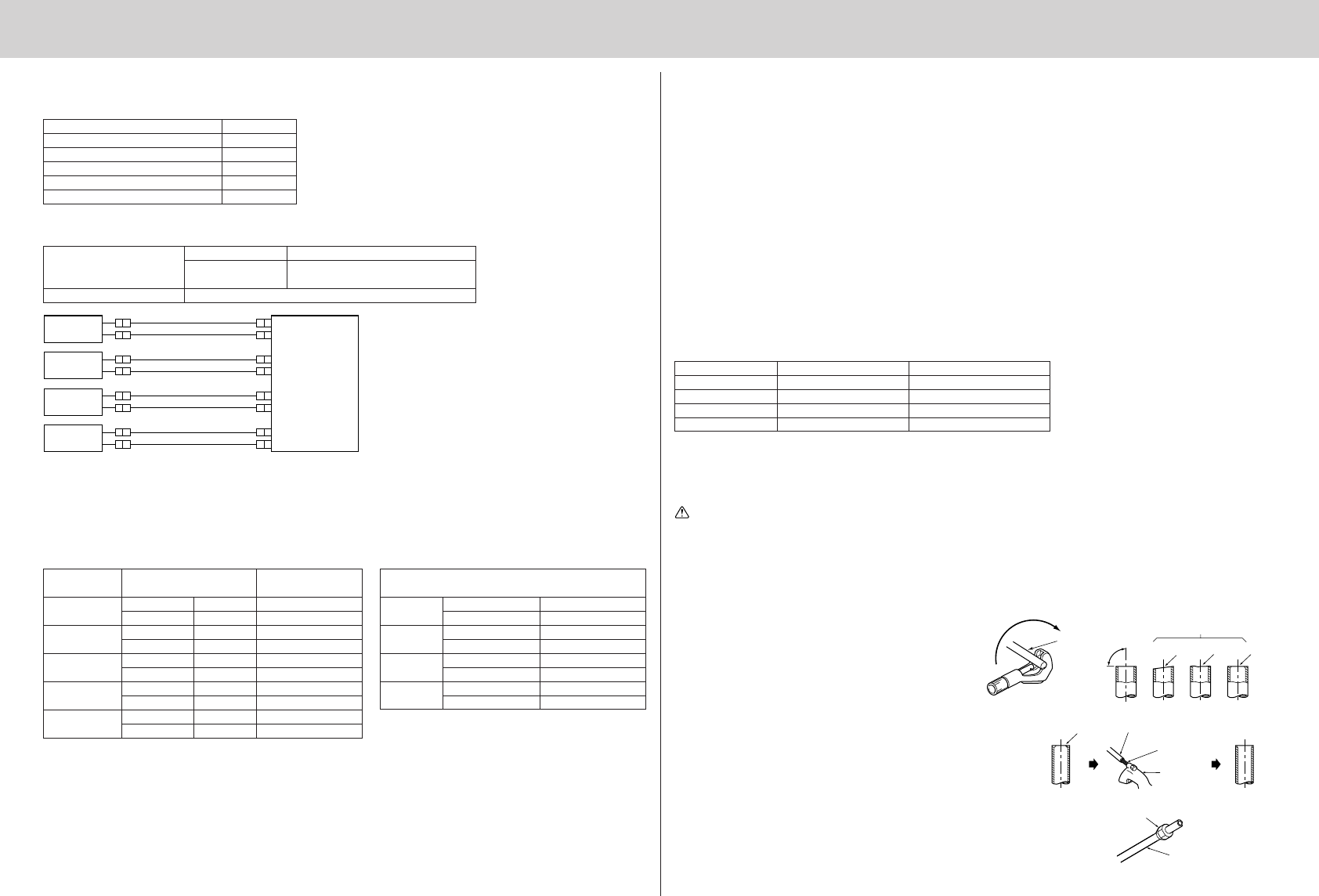
Copper
pipe
Good
No good
Tilted Uneven
Burred
Burr
Copper pipe
Spare
reamer
Pipe cutter
Flare nut
Copper pipe
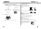
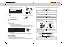
5-2 FLARING WORK
• Main cause of gas leakage is defect in flaring work.
Perform flaring work correctly in the following procedure.
1. Pipe cutting
• Cut the copper pipe correctly with pipe cutter.
2. Burrs removal
• Completely remove all burrs from the cut cross
section of the pipe.
• Put the end of the copper pipe downward to pre-
vent burrs from dropping in the pipe.
3. Putting nut on
• Remove flare nuts attached to indoor and outdoor
units, then put them on pipe having completed
burr removal.
(not possible to put them on after flaring work)
• Flare nut for R410A pipe may differ from R22 pipe
depending on the diameter of pipe.
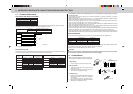
* Connections at outdoor unit are described as unit A, B, C and D below corresponding to the indica-
tion on each valve.
• If the diameter of connection pipes does not match the diameter of pipe end connections, use optional
different-diameter joints.
• When connecting the model 50 to either unit B, C or D, use optional different-diameter joints MAC-A454JP
because the valve size of gas pipes for the outdoor unit is ø9.52 mm.
• When connecting the model 22, 25 or 35 to unit A, use optional different-diameter joints MAC-A455JP be-
cause the valve size of gas pipes for the outdoor unit is ø12.7 mm.
• When connecting the model 60 to unit A, use optional different-diameter joints MAC-A456JP because the
valve size of gas pipes for the outdoor unit is ø12.7 mm.
• When connecting the model 60 to either unit B, C or D, use optional different-diameter joints PAC-SG76RJ
because the valve size of gas pipes for the outdoor unit is ø9.52 mm.
• When connecting the model 71 to unit A, use optional different-diameter joints MAC-A456JP and PAC-493PI
because the valve size of gas pipe and liquid pipe for the outdoor unit is ø12.7 mm and ø6.35 mm.
• When connecting the model 71 to either unit B, C or D, use optional different-diameter joints PAC-SG76RJ and
PAC-493PI because the valve size of gas pipe and liquid pipe for the outdoor unit is ø9.52 mm and ø6.35 mm.
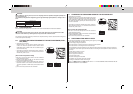
PIPING PREPARATION
1If you use commercially available copper pipes, use the following table for pipe specifications.
Outside diameter Wall thickness
Liquid pipe ø6.35 mm 0.8 mm
Gas pipe ø9.52 mm 0.8 mm
Gas pipe ø12.7 mm 1.0 mm
Gas pipe ø15.88 mm 1.0 mm
2For insulation material, use 8 mm-thick heat-insulating expended polyethylene with a specific gravity of 0.045.
3Ensure that the 2 refrigerant pipes are insulated to prevent condensation.
4Refrigerant pipe bending radius must be 100 mm or more.
CAUTION:
Be sure to use the insulation of specified thickness. Excessive thickness may cause incorrect installa-
tion of the indoor unit and lack of thickness may cause dew drippage.
90°
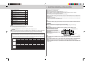
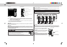
5. INDOOR/OUTDOOR UNITS CONNECTION FINISHING AND TEST RUN
Model
Pipe size for indoor unit
Allowable
name connection pipe size
22 Liquid pipe ø6.35 mm ø6.35 mm
25 Gas pipe ø9.52 mm ø9.52 mm
35
Liquid pipe ø6.35 mm ø6.35 mm
Gas pipe ø9.52 mm ø9.52 mm
50
Liquid pipe ø6.35 mm ø6.35 mm
Gas pipe ø12.7 mm ø12.7 mm
60
Liquid pipe ø6.35 mm ø6.35 mm
Gas pipe ø15.88 mm ø15.88 mm
71
Liquid pipe ø9.52 mm ø9.52 mm
Gas pipe ø15.88 mm ø15.88 mm
Valve size for outdoor unit
Å UNIT
Liquid pipe ø6.35 mm
Gas pipe ø12.7 mm
ı UNIT
Liquid pipe ø6.35 mm
Gas pipe ø9.52 mm
Ç UNIT
Liquid pipe ø6.35 mm
Gas pipe ø9.52 mm
Î UNIT
Liquid pipe ø6.35 mm
Gas pipe ø9.52 mm
Indoor unit Î UNIT
Indoor unit Ç UNIT
Outdoor
unit
Indoor unit ı UNIT
Indoor unit Å UNIT
5-1 FLARED CONNECTIONS
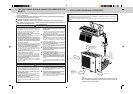
PIPE LENGTH AND HEIGHT DIFFERENCE
Limits 4A80VA
Pipe length per indoor unit 25 m max.
Total pipe length for multi-system 70 m max.
Height difference 10 m max.
No. of bends per indoor unit 25 max.
Total No. of bends for multi-system 70 max.
Refrigerant adjustment .......If pipe length exceeds 40 m, additional refrigerant (R410A) charge is required.
(The outdoor unit is charged with refrigerant for total pipe length up to 40 m.)
Pipe length
Up to 40 m No additional charge is required.
Exceeding 40 m
Additional charge is required.
(Refer to the table below.)
Refrigerant to be added 20 g/m × (refrigerant piping length(m)-40)
• For pipe size, see the table below.
SELECTING PIPE SIZE
The diameter of connection pipes differs according to the type and capacity of indoor units. Match the diameters
of connection pipes for indoor and outdoor units according to the following table.
(MXZ-4A80VA)