


5
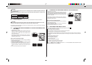
Connect to the supply terminals and leave a contact separation of at least 3 mm at each pole to
disconnect the source power pole. (When the power switch is shut off, it must disconnect all poles.)
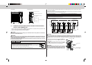
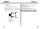
<Front View> <Right Side View>
35 mm
15 mm
Indoor/Outdoor unit
connecting wire B
Cable clamp
Power supply cord A
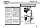
4-4 INDOOR/OUTDOOR WIRE CONNECTION AND OUTDOOR POWER
SUPPLY CORD CONNECTION
• Be sure to lead in the power supply cord A to the air conditioner in accordance with the specification table
below and “Technical Standards for Electrical Installation”.
• Be sure to use special circuits for room air conditioner.
CAUTION:
Attach an earth leakage breaker according to your installation location. If any breaker is not attached, it
may cause a risk of electric shock.
WARNING:
Be sure to comply with “Technical Standards for Electrical Installation”, follow this manual and use
special circuits for electrical work. If there is a lack of circuit capacity or some deficiency in installation,
it may cause a risk of fire or electric shock.
Overcurrent that might be produced may include DC substances. Be careful to choose the correct type
of overcurrent protection switch.
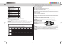
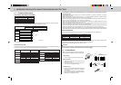
Rated Voltage Breaker capacity
230 V 25 A
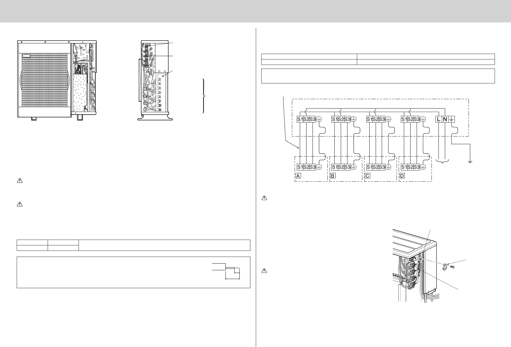
• Peel off both ends of the cables as shown in the right.
• Take care not to let the cables contact the pipes inside the unit.
• Take enough care to connect the indoor/outdoor unit connecting wire correctly be-
tween the respective indoor units and the outdoor unit.
• Make earth wire a little longer than the others. (more than 35 mm)
• For the power supply cord and the indoor/outdoor unit connecting wires, be sure to use the ones in compli-
ance with the standards.
• Be sure to push the core until it is hidden and pull each cable to make sure that it is not pulled up. Incomplete
insertion may cause a risk of burning the terminal blocks.
Power supply cord Specification Cable 3-core 2.5 mm
2
, in conformity with Design 245 IEC 57.
Indoor and Outdoor connecting wire Specification Cable 4-core 1.0/1.5 mm
2
, in conformity with Design 245 IEC 57.
This installation manual is only for the outdoor unit installation. In installing the indoor units, refer to the
installation manual attached to each indoor unit.
WARNING:
Use the indoor/outdoor unit connecting wire that meets the Standards to connect the indoor and out-
door units and fix the wire to the terminal block securely so that no external force is conveyed to the
connecting section of the terminal block. Incomplete connection or fixing of the wire could result in a
fire.
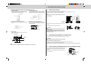
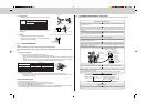
• Give extra length to both power supply cord A and in-
door/outdoor unit connecting wire B taking later service
into account.
• After making connections between both power supply
cord A and indoor/outdoor unit connecting wire B, be
sure to fix both cable and wire with cable clamps.
WARNING:
Be sure to attach the terminal block covers (panel) of
both indoor and outdoor units. If there is some defi-
ciency in terminal block cover (panel) attachment, it may
cause a risk of fire or electric shock due to dust or wa-
ter.
Connection pipe connections
Power cable terminal block
Indoor/Outdoor connecting terminal block
Opening for power cable and indoor/out-
door connecting wire
Liquid
Î UNIT
GAS
Liquid
Ç UNIT
GAS
Liquid
ı UNIT
GAS
Liquid
Å UNIT
GAS
Indoor/outdoor unit connecting wire
<OUTDOOR UNIT>
POWER SUPPLY
~/N 230 V 50 Hz
UNIT UNIT
UNIT
UNIT