


En-6
4-3.TESTRUN
• Testrunsoftheindoorunitsshouldbeperformedindividually.Seetheinstallationmanual
comingwiththeindoorunit,andmakesurealltheunitsoperateproperly.
• If the test run with all the units is performed at once, possible erroneous connections of the
refrigerantpipesandtheindoor/outdoorunitconnectingwirescannotbedetected.Thus,be
sure to perform the test run one by one.
About the restart protective mechanism
Oncethecompressorstops,therestartpreventivedeviceoperatessothecompressorwillnot
operatefor3minutestoprotecttheairconditioner.
Wiring/piping correction function
Thisunithasawiring/pipingcorrectionfunctionwhichcorrectswiringandpipingcombination.
Whenthereispossibilityofincorrectwiringandpipingcombination,andconrmingthecombi
-
nationisdifcult,usethisfunctiontodetectandcorrectthecombinationbyfollowingtheproce
-
dures below.
Makesurethatthefollowingisdone.
• Power is supplied to the unit.
• Stopvalvesareopen.
Note:
During detection, the operation of the indoor unit is controlled by the outdoor unit. During detec
-
tion, the indoor unit automatically stops operation. This is not a malfunction.
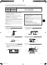
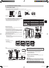
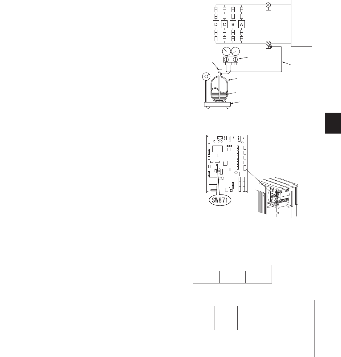
4-2.GASCHARGE
Perform gas charge to unit.
1)Connectgascylindertotheserviceportofstopvalve.
2)Performairpurgeofthepipe(orhose)comingfromrefrigerantgascylinder.
3)Replenishspeciedamountoftherefrigerant,whileoperatingtheairconditionerforcooling.
Note:
Incaseofaddingrefrigerant,complywiththequantityspeciedfortherefrigeratingcycle.
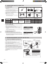
CAUTION:
When charging the refrigerant system with additional refrigerant, be sure to use liquid refriger
-
ant. Adding gas refrigerant may change the composition of the refrigerant in the system and
affect normal operation of the air conditioner. Also, charge the liquid refrigerant slowly, otherwise
thecompressorwillbelocked.
To maintain the high pressure of the gas cylinder, warm the gas cylinder with warm water (under
40°C(140°F))duringcoldseason.Butneverusenakedreorsteam.
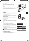
Procedure
Pressthepiping/wiringcorrectionswitch(SW871)1minuteormoreafterturningonthepower
supply.
• Correction completes in 10 to 15 minutes. When the correction is completed, its result is
shown by LED indication. Details are described in the following table.
• Tocancelthisfunctionduringitsoperation,pressthepiping/wiringcorrectionswitch(SW871)
again.
• Whenthecorrectioncompletedwithouterror,donotpressthepiping/wiringcorrectionswitch
(SW871)again.
Whentheresultwas“cannotbecorrected”,pressthepiping/wiringcorrectionswitch(SW871)
againtocancelthisfunction.Then,conrmthewiringandpipingcombinationinaconventional
manner by operating the indoor units one by one.
• Theoperationisdonewhilethepowerissupplied.Makesurenottocontactpartsotherthan
theswitch,includingtheP.C.board.Thismaycauseelectricshockorburnbyhotpartsand
livepartsaroundtheswitch.ContactingthelivepartsmaycauseP.C.boarddamage.
• TopreventelectroniccontrolP.C.boarddamage,makesuretoperformstaticeliminationbe
-
fore operating this function.
• Thisfunctiondoesnotoperatewhentheoutsidetemperatureis0°C(32°F)orbelow.
LEDindicationduringdetection:
LED
1(Red) 2(Yellow) 3(Green)
Lighted Lighted Blinking
Resultofpiping/wiringcorrectionfunction
LED
Result
1(Red) 2(Yellow) 3(Green)
Lighted Not lighted Lighted
Completed
(Correctedsuccessfully)
Blinking Blinking Blinking Cannot be corrected
Other indications
Refer to “SAFETY PRE-
CAUTIONS WHEN LED
FLASHES”locatedbehind
theservicepanel.
4-4.EXPLANATIONTOTHEUSER
• UsingtheOPERATINGINSTRUCTIONS,explaintotheuserhowtousetheairconditioner(howtousetheremotecontroller,howtoremovetheairlters,howto
removeorputtheremotecontrollerintheremotecontrollerholder,howtoclean,precautionsforoperation,etc.).
• Recommend the user to read the OPERATING INSTRUCTIONS carefully.
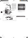
Union
Stopvalve
Liquid
pipe
Indoor
unit
Stopvalvewith
serviceport
Gas
pipe
Refrigerant gas
cylinder
operatingvalve
(forR410A)
Gauge manifold
valve(forR410A)
Charge hose
(forR410A)
Refrigerant gas cylinder for R410A with siphon
Electronic scale for refrigerant charging
Refrigerant(liquid)
Outdoor
unit
Union
Union
Union
D unit is for
4B36NAonly
JG79A417H01_en.indd 6 10/12/2010 9:19:47 AM