


En-5
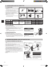
3-2.PIPECONNECTION
1)Applyathincoatofrefrigerationoil(G)tothearedendsofthepipesand
the pipe connections of the outdoor unit.
2)Alignthecenterofthepipewiththatofthepipeconnectionsoftheoutdoor
unit,thenhandtightenthearenut3to4turns.
3)Tightenthearenutwithatorquewrenchasspeciedinthetable.
•Over-tighteningmaycausedamagetothearenut,resultinginrefriger
-
antleakage.
• Be sure to wrap insulation around the piping. Direct contact with the bare
piping may result in burns or frostbite.
3-3.INSULATIONANDTAPING
1)Coverpipingjointswithpipecover.
2)Foroutdoorunitside,surelyinsulateeverypipingincludingvalves.
3)Usingpipingtape(E),applytapingstartingfromtheentryofoutdoorunit.
•Stoptheendofpipingtape(E)withtape(withadhesiveagentattached).
•Whenpipinghavetobearrangedthroughaboveceiling,closetorwhere
the temperature and humidity are high, wind additional commercially sold
insulationtopreventcondensation.
WARNING
When installing the unit, securely
connect the refrigerant pipes before
starting the compressor.
CAUTION
When there are the ports which are
not used, make sure their nuts are
tightened securely.
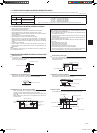
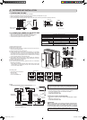
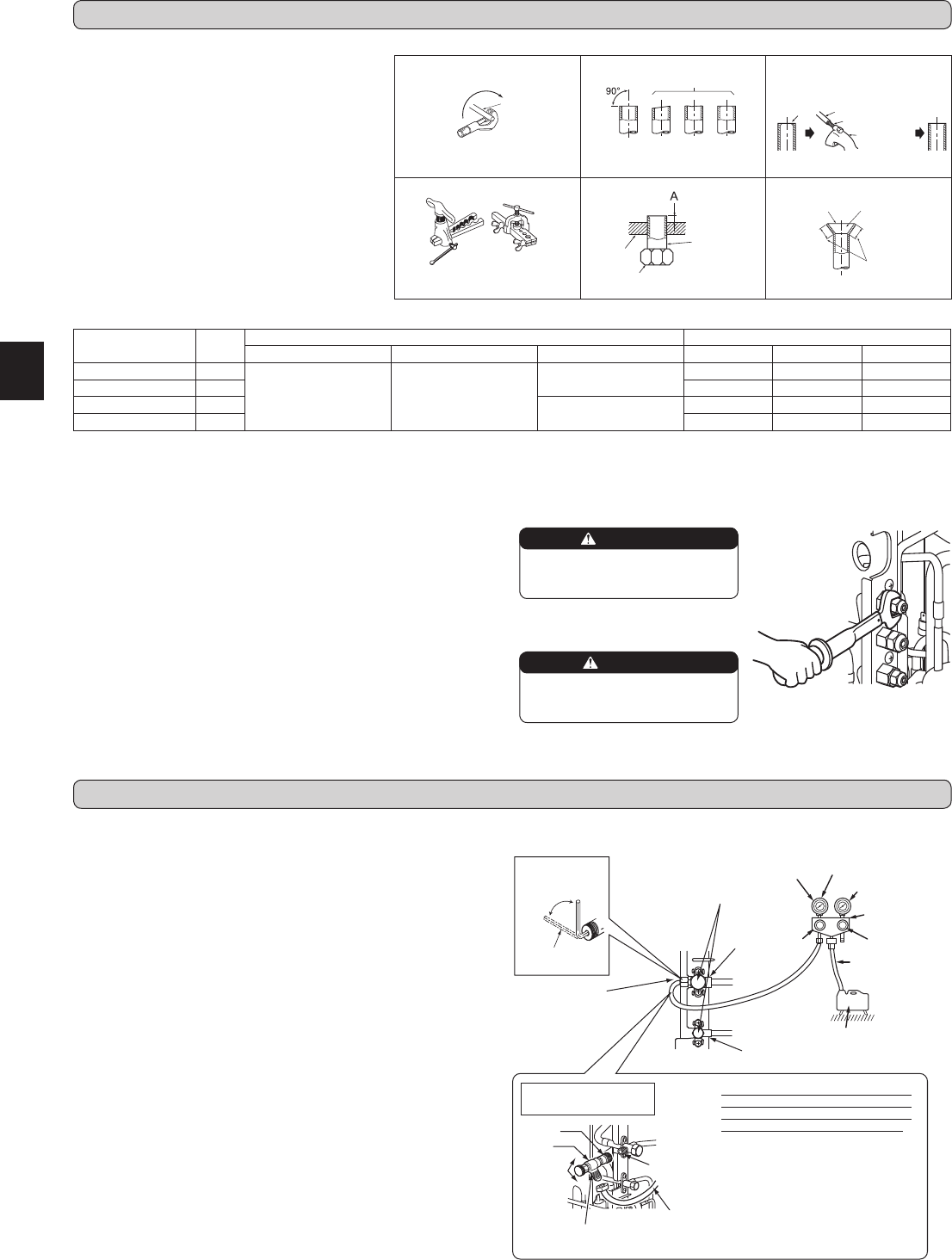
Fig. 1 Fig. 2 Fig.3
Fig. 4 Fig. 5 Fig. 6
TiltedUnevenBurred
Good
No good
Burr
Copper pipe
Spare reamer
Pipe cutter
Smooth all
around
Evenlength
all around
Inside is shin
-
ing without any
scratches.
Flare nut
Die
Copper pipe
Clutch type
Flaring tool
Wing nut type
Copper
pipe
Pipe diameter
[mm(inch)]
Nut
(mm)
A[mm(inch)] Tightening torque
Clutch type tool for R410A Clutch type tool for R22 Wing nut type tool for R22
N•m kgf•cm ft•Ib
ø6.35(1/4) 17
0 to 0.5
(0to0.02)
1.0 to 1.5
(0.04to0.06)
1.5 to 2.0
(0.06to0.08)
13.7to17.7 140 to 180 10to13
ø9.52(3/8)
22 34.3to41.2 350to420 25to30
ø12.7(1/2)
26
2.0 to 2.5
(0.08to1.0)
49.0 to 56.4 500 to 575 36to42
ø15.88(5/8)
29 73.5to78.4 750 to 800 54 to 58
3. FLARINGWORKANDPIPECONNECTION
3-1.FLARINGWORK
1)Cutthecopperpipecorrectlywithpipecutter.(Fig.1,2)
2)Completelyremoveallburrsfromthecutcrosssection
ofpipe.(Fig.3)
•Aimthecopperpipedownwardwhileremovingburrs
topreventburrsfromdroppinginthepipe.
3)Removearenutsattachedtoindoorandoutdoorunits,
thenputthemonpipehavingcompletedburrremoval.
(Notpossibletoputthemonafteraringwork.)
4)Flaringwork(Fig.4,5).Firmlyholdcopperpipeinthe
dimension shown in the table. Select A mm from the
table according to the tool selected.
5)Check
•ComparethearedworkwithFig.6.
•Ifareisnotedtobedefective,cutoffthearedsec
-
tionanddoaringworkagain.
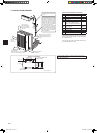
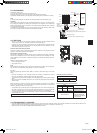
4-1.PURGINGPROCEDURESANDLEAKTEST
4. PURGINGPROCEDURES,LEAKTEST,ANDTESTRUN
1)Removeserviceportcapofstopvalveonthesideoftheoutdoorunitgas
pipe.(Thestopvalvesarefullyclosedandcoveredincapsintheirinitial
state.)
2)Connectgaugemanifoldvalveandvacuumpumptoserviceportofstop
valveonthegaspipesideoftheoutdoorunit.
3)Runthevacuumpump.(Vacuumizeformorethan15minutes.)
4)Checkthevacuumwithgaugemanifoldvalve,thenclosegaugemanifold
valve,andstopthevacuumpump.
5)Leaveasitisforoneortwominutes.Makesurethepointerofgauge
manifoldvalveremainsinthesameposition.Conrmthatpressuregauge
shows
–
0.101MPa[Gauge](
–
760mmHg)(
–
30in.Hg).
6)Removegaugemanifoldvalvequicklyfromserviceportofstopvalve.
7)Fullyopenallstopvalvesonthegaspipeandtheliquidpipe.Operating
without fully opening lowers the performance and this causes trouble.
8)Referto1-2.,andchargetheprescribedamountofrefrigerantifneeded.
Be sure to charge slowly with liquid refrigerant. Otherwise, composition of
the refrigerant in the system may be changed and affect performance of
the air conditioner.
9)Tightencapofserviceporttoobtaintheinitialstatus.
10
)Leaktest
Serviceportcap
(Torque13.7to
17.7 N•m, 140 to
180kgf
•cm, 10 to
13
ft•lb)
Stopvalve
for GAS
Stopvalvecap
(Torque 19.6 to 29.4 N•m,
200to300kgf•cm,15to
22ft•lb)
Gauge manifold
valve(forR410A)
Compound pressure
gauge(forR410A)
–0.101MPa
[–760 mmHg
(–30in.Hg)]
Handle
Low
Handle High
Vacuumpump
(forR410A)
Charge hose
(forR410A)
*Close
*Open
Hexagonal wrench
*4 to 5 turns
Stopvalve
for LIQUID
Pressure gauge
(forR410A)
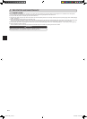
Precautions when using
thecontrolvalve
Whenattachingthecontrolvalveto
theserviceport,valvecoremayde-
form or loosen if excess pressure is
applied.Thismaycausegasleak.
Serviceport
Charge hose
(forR410A)
Body
Close
Open
Control
valve
A
Whenattachingthecontrolvalveto
theserviceport,makesurethatthe
valvecoreisinclosedposition,and
then tighten part A. Do not tighten
partAorturnthebodywhenvalve
core is in open position.
JG79A417H01_en.indd 5 10/12/2010 9:19:46 AM