


En-4
2. OUTDOORUNITINSTALLATION
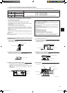
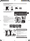
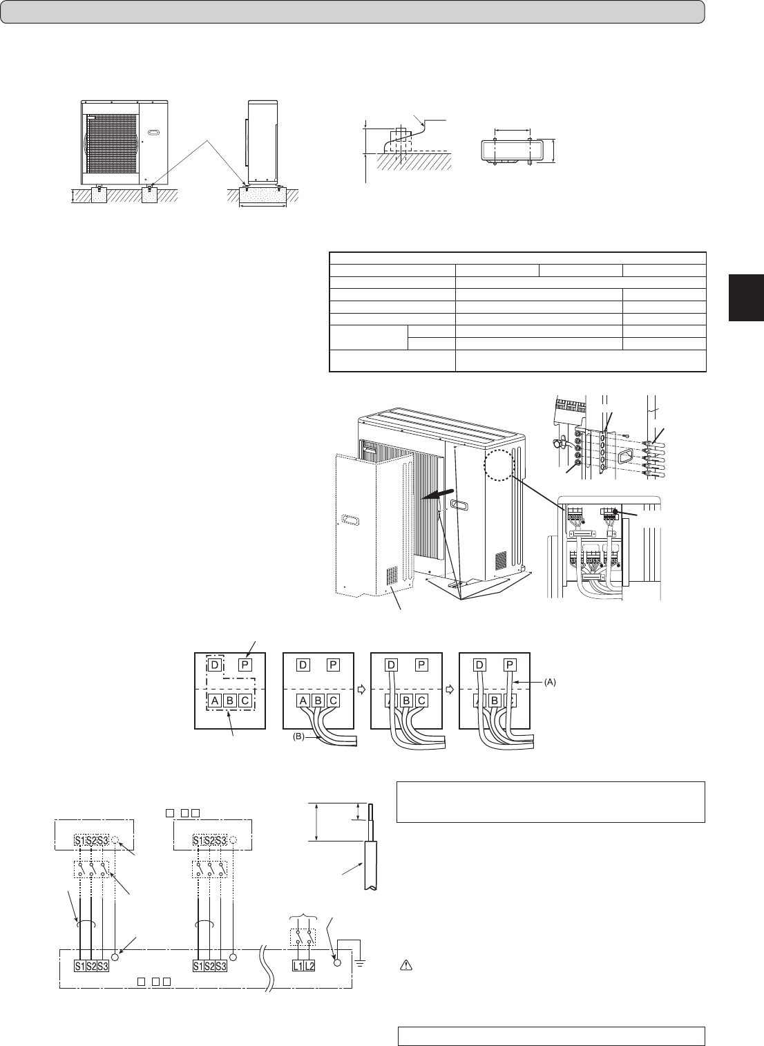
2-1.INSTALLINGTHEUNIT
Fix here with
M10 bolts.
Makethesetting
depth deeper.
Makewithwider.
Anchor leg
25(31/32)orless
Anchor both length
Anchor both pitch
(Unit:mm(inch))
• Besuretoxtheunit’slegswithboltswheninstallingit.
• Besuretoinstalltheunitrmlytoensurethatitdoesnotfallbyanearthquakeoragust.
• Refertothegureintherightforconcretefoundation.
• Donotusethedrainsocketandthedraincapsinthecoldregion.Drainmayfreezeanditmakesthefanstop.
500
(19-11/16)
330(13)
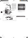
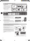
2-2.CONNECTINGWIRESFOROUTDOORUNIT
• Be sure to use special circuits for room air conditioner.
• Wiringworkshouldbebasedonapplicabletechnicalstandards.
• Wiring connections should be made following the diagram.
• Screws should be tightened so they won’t loosen.
ELECTRICAL SPECIFICATIONS
OUTDOOR UNIT
MXZ-3B24NA MXZ-3B30NA MXZ-4B36NA
Powersupply(V,PHASE,Hz) 208/230,1,60
Max.Fusesize(timedelay)(A)
20 25
Min.CircuitAmpacity(A) 18
23
Fanmotor(F.L.A)
0.93 0.93
Compressor
(R.L.A) 11 14.4
(L.R.A) 15 15
Controlvoltage
Indoorunit-Remotecontroller:(Wireless)
Indoorunit-Outdoorunit:DC12-24V
35mm
(1-3/8in.)
15 mm
(5/8in.)
Lead wire
1)Removetheservicepanel.
2)Removetheconduitcover.
3)Attachtheconduitconnectortoconduitcoverwithlocknutthense
-
cure it to the unit with screws.
4)ConnectgroundwirestotheTBsupport.
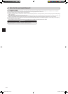
5)Loosenterminalscrew,andconnectindoor/outdoorunitconnecting
wire(B)fromtheindoorunitcorrectlyontheterminalblock.Becareful
nottomakemis-wiring.Fixthewiretotheterminalblocksecurelyso
thatnopartofitscoreisappeared,andnoexternalforceisconveyed
totheconnectingsectionoftheterminalblock.
6)Firmlytightentheterminalscrewstopreventthemfromloosening.
Aftertightening,pullthewireslightlytoconrmthattheydonotmove.
7)Perform5)and6)foreachindoorunit.
8)Connectpowersupplycord(A).
9)Closetheservicepanelsecurely.Makesurethat3-2.PIPECON
-
NECTION is completed.
•Aftermakingconnectionsbetweenbothpowersupplycord(A)and
indoor/outdoorunitconnectingwire(B),besuretoxbothcable
and wire with cable clamps.
Connecting order
• Connecttheterminalblockin
following order.
A
→
B
→
C
→
D
→
P
CONNECTINGWIRESANDCONNECTINGGROUNDWIRE
• Use solid conductor AWG14 or stranded conductor AWG14.
• Usedoubleinsulatedcopperwirewith600Vinsulation.
• Use copper conductors only.
* Follow local electrical code.
POWERSUPPLYCABLEANDGROUNDWIRE
• UsesolidorstrandedconductorAWG14(MXZ-3B)/AWG12(MXZ-
4B).
• Use copper conductors only.
* Follow local electrical code.
WARNING:
Use the indoor/outdoor unit connecting wire that meets the Stand-
ardstoconnecttheindoorandoutdoorunitsandxthewireto
the terminal block securely so that no external force is conveyed
to the connecting section of the terminal block. An incomplete
connectionorxingofthewirecouldresultinare.
Remark:
* Adisconnectswitchshouldberequired.Checkthelocalcode.
** Use a ring tongue terminal in order to connect a ground wire to terminal.
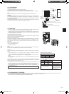
• Connect wires to the matching numbers of terminals.
• Be sure to attach each screw to its correspondent terminal
when securing the cord and/or the wire to the terminal block.
Terminalblock
Grounding
terminal **
208/230VAC
1phase60Hz
Grounding
terminal **
Terminalblock1
Ground
OUTDOOR UNIT
Power supply
208/230VAC
1 phase 2 wires 60 Hz
Disconnect
switch *
Grounding
terminal **
Terminalblock Terminalblock
INDOOR UNIT
Terminalblock
Forfutureservicing,giveextralengthtotheconnectingwires.
Servicepanel
Screws
4B36NA
Terminalblock
for power supply
Power supply
Terminalblockfor
indoor/outdoorunit
A – C D
Locknut
Conduitcover
Connector
Dunitisfor4B36NAonly
Dunitisfor4B36NAonly
A – C D
JG79A417H01_en.indd 4 10/12/2010 9:19:45 AM