


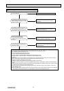
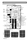
OPERATING PROCEDURE
PHOTOS
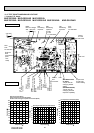
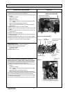
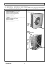
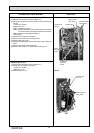
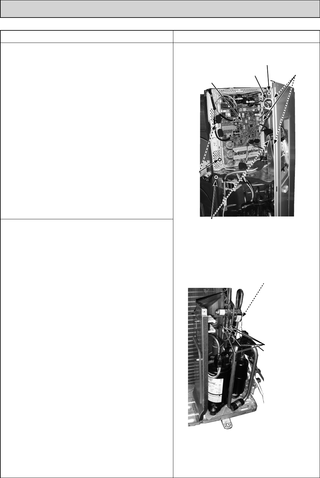
2. Removing the inverter assembly, inverter P.C. board
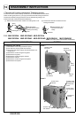
(1) Remove the cabinet and panels. (Refer to 1.)
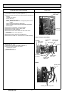
(2) Disconnect the lead wire to the reactor and the following con-
nectors:
<Inverter P.C. board>
CN602 (R.V. coil)
CN931, CN932 (Fan motor)
CN671 (Defrost thermistor, discharge temperature thermistor
and outdoor heat exchanger temperature thermistor)
CN672 (Ambient temperature thermistor)
CN724 (LEV)
(3) Remove the compressor connector.
(4) Remove the screws fixing the relay panel.
(5) Remove the relay panel.
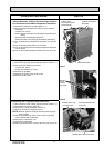
(6) Remove the earth wires and the lead wires of the inverter P.C.
board.
(7) Remove the screw of the PB support.
(8) Remove the inverter P.C. board from the relay panel.
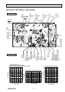
Photo 3
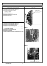
Photo 4
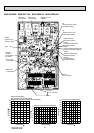
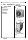
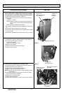
3. Removing R.V. coil
(1) Remove the cabinet and panels. (Refer to 1.)
(2) Disconnect the following connector:
<Inverter P.C. board>
CN602 (R.V. coil)
(3) Remove the R.V. coil.
93
Screws of the
PB support
Screws of
the relay
panel
Inverter P.C
board
Earth wires
Screw of the
relay panel
Screws
of the PB
support
Brazed parts of
4-way valve
Screw of the
R.V. coil
OBH532E