


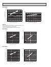
99
6
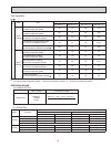
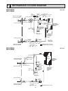
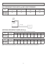
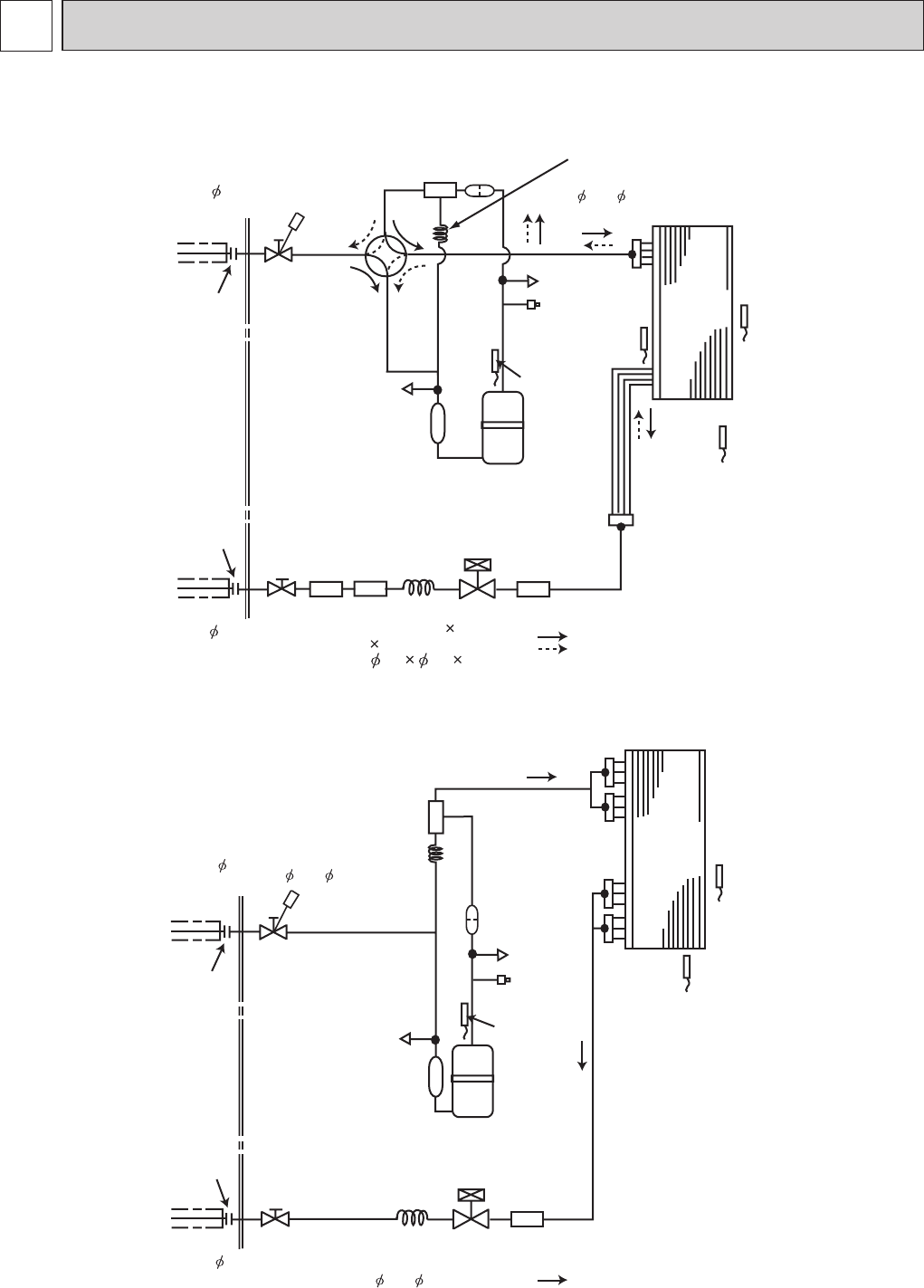
REFRIGERANT SYSTEM DIAGRAM
Unit:inch
MUZ-D30NA
MUZ-D36NA
MUY-D30NA
MUY-D36NA
Outdoor
heat
exchanger
Flared connection
Defrost
thermistor
RT61
Service
port
Service
port
Discharge
temperature
thermistor
RT62
Flared connection
Stop valve
Stop valve
(with service port)
Capillary tube
Refrigerant flow in cooling
Compressor
4-way valve
Refrigerant flow in heating
LEV
R.V. coil
heating ON
cooling OFF
Strainer
#100
Receiver
Outdoor heat
exchanger
temperature
thermistor
RT68
Ambient
temperature
thermistor
RT65
Strainer
#100
Refrigerant pipe
5/8
(with heat insulator)
Refrigerant pipe 3/8
(with heat insulator)
O.D. 0.142 I.D. 0.094
1-31/32
(
3.6 2.4 50
)
Oil
separator
Strainer
#100
High-pressure
Switch
Capillary tube
O.D. 0.071 x I.D. 0.024
x 39-3/8
( 1.8 x 0.6 x 1,000)
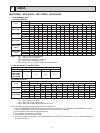
Unit:inch
O.D. 0.142 x I.D. 0.094
x 1-31/32
( 3.6 x 2.4 x 50)
Capillary tube
High-pressure
Switch
Flared connection
Discharge
temperature
thermistor
RT62
Flared connection
Stop valve
Stop valve
(with service port)
Capillary tube
Refrigerant flow in cooling
Refrigerant pipe 5/8
(with heat insulator)
Refrigerant pipe 3/8
(with heat insulator)
Strainer
#100
Strainer
#100
Oil separator
Outdoor
heat
exchanger
Ambient
temperature
thermistor
RT65
Outdoor heat
exchanger
temperature
thermistor
RT68
Compressor
Service
port
LEV
Service
port
O.D. 0.071 x I.D. 0.024
x 39-3/8
( 1.8 x 0.6 x 1,000)