


27
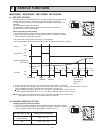
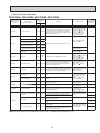
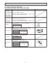
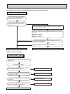
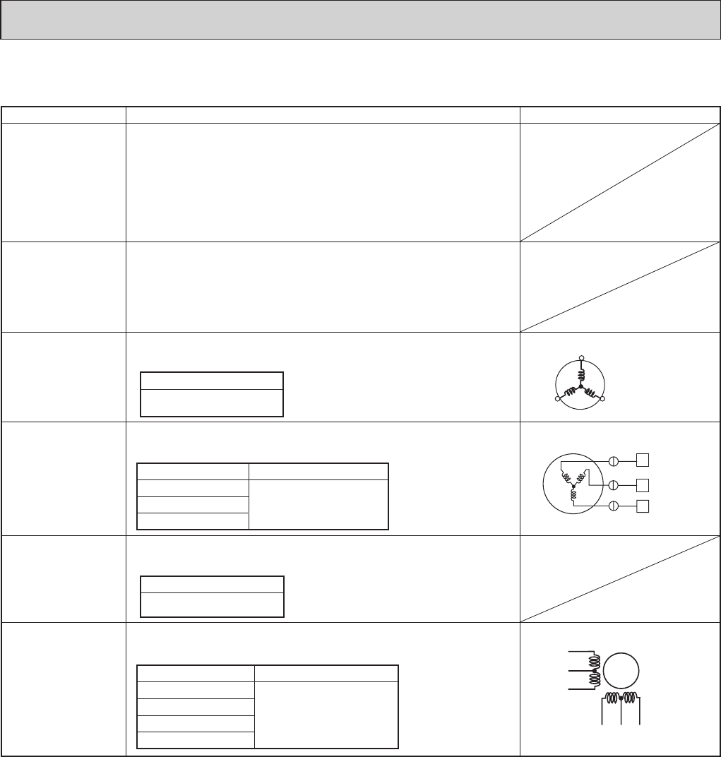
10-4. TROUBLE CRITERION OF MAIN PARTS
MUZ-D30NA MUZ-D36NA MUY-D30NA MUY-D36NA
Part name Check method and criterion Figure
Defrost thermistor
(RT61) (MUZ)
Ambient temperature
thermistor (RT65)
Outdoor heat ex-
changer temperature
thermistor (RT68)
Measure the resistance with a tester.
Refer to 10-6. “Test point diagram and voltage”, 1. “Outdoor electron-
ic control P.C. board”, the chart of thermistor.
Discharge tem-
perature thermistor
(RT62)
Fin temperature
thermistor (RT64)
Measure the resistance with a tester. Before measurement, hold the
thermistor with your hands to warm it up.
Refer to 10-6. “Test point diagram and voltage”, 1. “Outdoor electron-
ic control P.C. board”, the chart of thermistor.
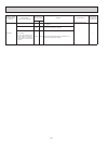
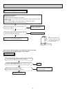
Compressor
Measure the resistance between terminals using a tester.
(Winding temperature : 14 ~ 104 °F (-10 ~ 40 °C))
Normal
1.24 ~ 1.53 Ω
Outdoor fan motor
Measure the resistance between lead wires using a tester.
(Part temperature : 14 ~ 104 °F (-10 ~ 40 °C))
Color of lead wire Normal
RED – BLK
13 ~ 16 ΩBLK – WHT
WHT – RED
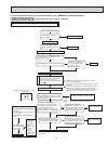
R. V. coil (MUZ)
Measure the resistance using a tester.
(Part temperature : 14 ~ 104 °F (-10 ~ 40 °C))
Normal
1.20 ~ 1.55 kΩ
Linear expansion
valve
Measure the resistance using a tester.
(Part temperature : 14 ~ 104 °F (-10 ~ 40 °C))
Color of lead wire Normal
WHT – RED
38 ~ 50 Ω
RED – ORN
YLW – BRN
BRN – BLU
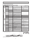
W
U
V
WHT
RED
BLK
LEV
WHT
RED
YLW
BRN
ORN
BLU
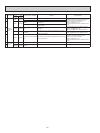
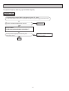
U
RED
WHT
BLK
V
W
(W)
(V)
(U)