


27
1. Indoor power P.C. board, Indoor terminal P.C. board
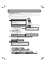
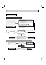
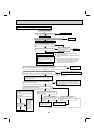
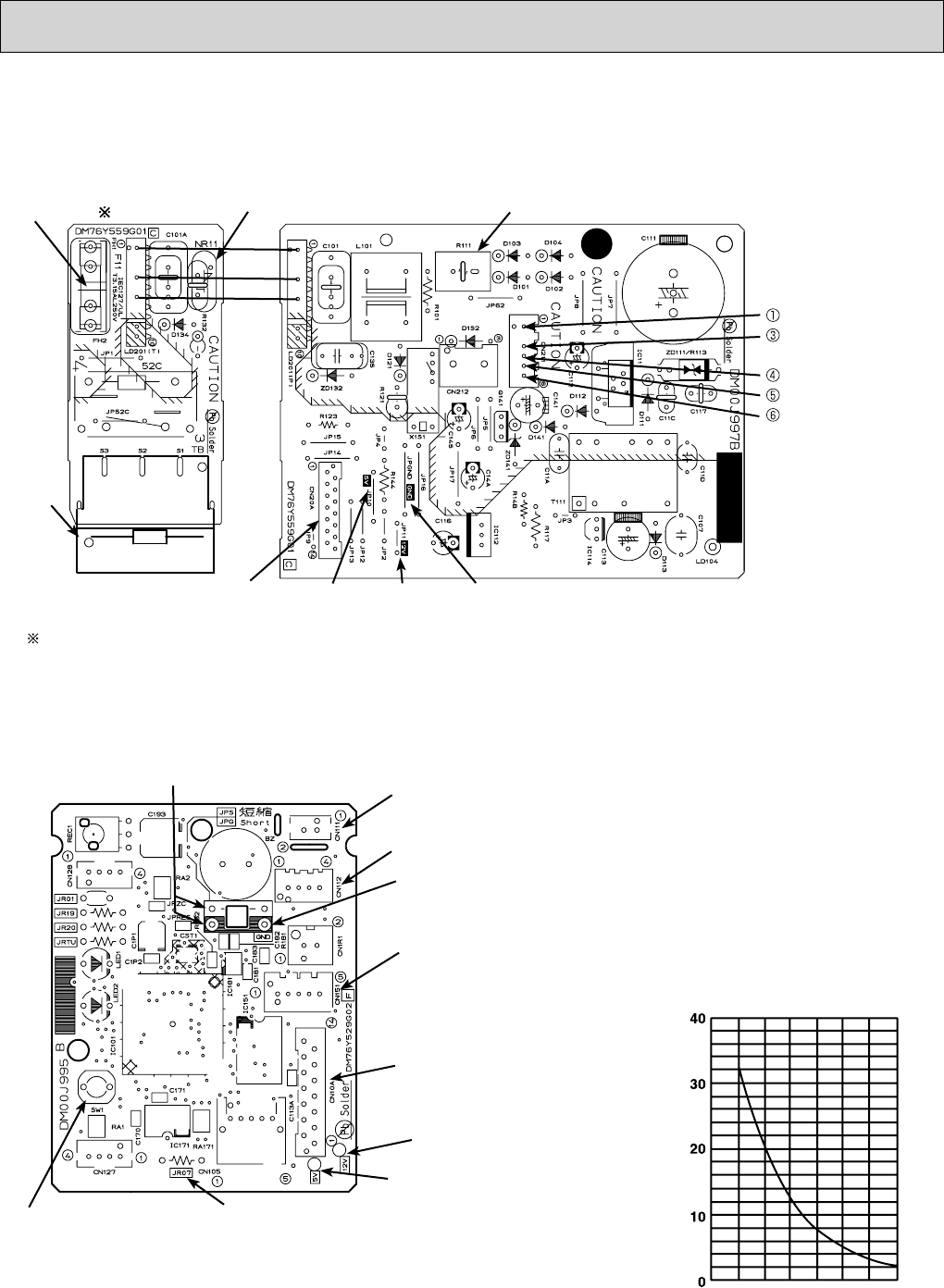
9-7. Test point diagram and voltage
Indoor terminal P.C. board Indoor power P.C. board
Please replace the fuse after removing the indoor terminal P.C. board from the electrical box.
Fuse (F11)( )
Varistor (NR11)
Terminal
block
Connector to indoor electronic
control P.C. board (CN20A)
5 VDC
12 VDC GND
Resistor (R111)
Indoor fan motor
(CN211)
294/325 VDC
(–) GND (high-
voltage DC)
15 VDC
(+)3-6 VDC
(+)0-6 V
Timer short mode point JPG JPS
(Refer to 7-1.)
Room temperature thermistor RT11 (CN111)
Indoor coil thermistor RT12, RT13 (CN112)
Vane motor (CN151)
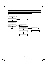
Connector to
Indoor power P.C. board
(CN10A)
12 VDC
5 VDC
Release of Auto restart function
Solder the Jumper wire to JR07
(Refer to 7-3.)
Emergency operation
switch (E.O.SW) (SW1)
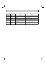
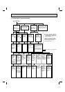
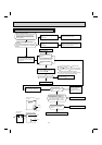
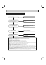
2. Indoor electronic control P.C. board
GND
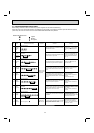
Room temperature thermistor (RT11)
Indoor coil thermistor (RT12, RT13)
Temperature (°F)
Resistance (kΩ)
32
50 68 86 104122 140