


19
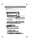
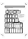
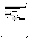
9-3. INSTRUCTION OF TROUBLESHOOTING
Indoor unit oper-
ates.
Outdoor unit
does not operate.
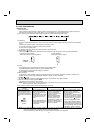
If blinking of OPERATION INDI-
CATOR lamp cannot be checked,
it can be checked with failure
mode recall function.
Indoor unit operates.
Outdoor unit does
not operate normally.
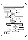
Indoor unit does
not receive the
signal from re-
mote controller.
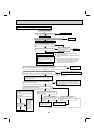
OPERATION INDICATOR
lamp on the indoor unit is
fl ashing ON and OFF.
Outdoor unit
operates only
in Test Run
operation.
Outdoor unit
does not
operate even
in Test Run
operation.
Unit does not
operate nor-
mal operation
in COOL or
HEAT mode.
Indoor unit
operates, when
EMERGENCY
OPERATION
switch is pressed.
Indoor unit does
not operate, when
EMERGENCY
OPERATION
switch is pressed.
Check room
temperature
thermistor.
Refer to 9-7.
"Test point
diagram and
voltage".
Refer to "How
to check
inverter/com-
pressor".
Refer to
"Check of R.V.
coil".
Refer to 9-6.
"Check of remote
controller and
indoor elec-
tronic control P.C.
board".
1. Check indoor/out-
door connecting wire.
(Check if the power is
supplied to the indoor
unit.)
2. Refer to 9-6.
"Check
of indoor P.C. board
and indoor fan motor".
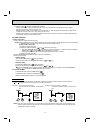
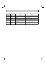
Upper lamp
Flash ON
and OFF at
0.5-second
intervals
Cause:
Indoor/Outdoor
unit
• Miswiring or
trouble of
serial signal.
Upper lamp
2-time fl ash
Cause:
Indoor unit
• Trouble
of room
temperature
/ indoor coil
thermistor.
Upper lamp
3-time fl ash
Cause:
Indoor unit
• Trouble of
indoor fan
motor.
Upper lamp
4-time fl ash
Cause:
Indoor unit
• Trouble
of indoor
unit control
system.
Upper lamp
5-time fl ash
Cause:
Outdoor unit
• Outdoor
power sys-
tem abnor-
mality.
Upper lamp
6-time fl ash
Cause:
Outdoor unit
• Trouble of
thermistor in
outdoor unit.
Upper lamp
7-time fl ash
Cause:
Outdoor unit
• Trouble of
outdoor con-
trol system.
Upper lamp
14-time fl ash
Cause:
Outdoor unit
• Other ab-
normality
Start
Refer to 9-6.
"How to
check mis-
wiring and
serial signal
error".
Check room
temperature
thermistor
and indoor
coil thermis-
tor. Refer
to 9-7."Test
point diagram
and voltage".
Refer to 9-6.
"Check of
indoor fan
motor".
Replace the
indoor elec-
tronic control
P.C. board.
Refer to
"How to
check
inverter/com-
pressor".
Refer to
"Check of
outdoor ther-
mistors".
Replace the
inverter P.C.
board or
the outdoor
electronic
control P.C.
board.
Check "Flow
chart of the
detailed
outdoor unit
failure mode
recall func-
tion."
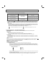
"Test Run operation" means the
operation within 30 minutes af-
ter EMERGENCY OPERATION
switch is pressed.
Refer to outdoor unit service manual.