13
Before taking measures, make sure that the symptom reappears for accurate troubleshooting.
Self check table
8-3. Troubleshooting check table
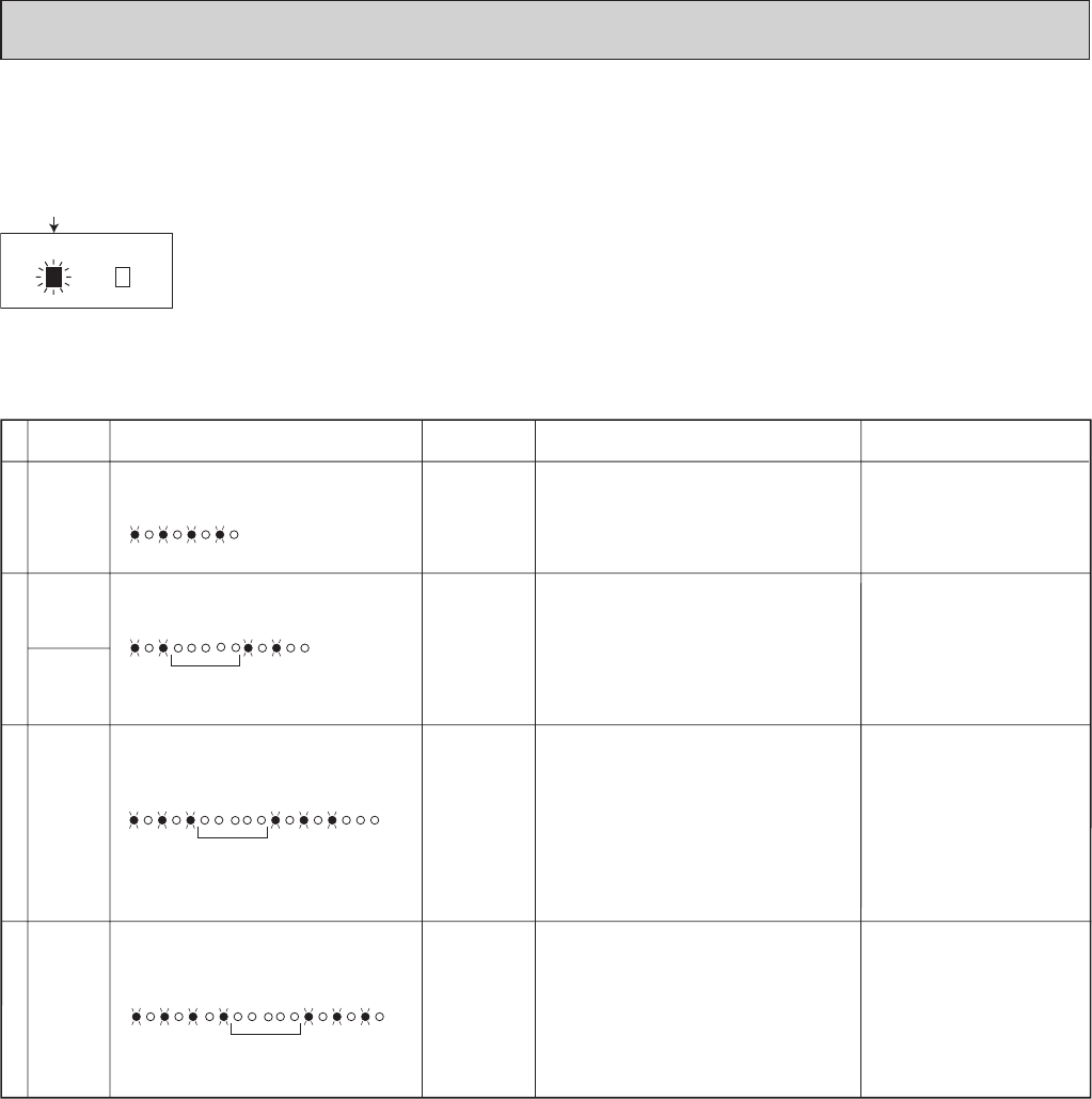
• The following indication applies regardless of shape of the indicator.
flashing
Operation Indicator
· Flashing of the OPERATION INDICATOR lamp (on the left)
indicates possible abnormalities.
· The OPERATION INDICATOR lamp (on the left) is
lighting during normal operation.
No.
2
SymptomIndication
Detection method
Check point
Indoor coil
thermistor
3
Indoor fan
motor.
Abnormal
point
Room
tempera-
ture
thermistor
2-time flash
2.5-second OFF
Detect Indoor coil/room temperature
thermistor short or open circuit every 8
seconds during operation.
• Refer to the characteristics of
indoor coil thermistor and
room temperature thermistor
shown in 8-6.
3-time flash
2.5-second OFF
Indoor fan
motor repeats
12 seconds
ON and 3
minutes OFF.
When the
indoor fan
motor breaks,
the fan keeps
stopping.
When rotational frequency feedback signal is
not emitting during 12-second indoor fan
operation.
• Refer to 8-5.A "Check of
indoor fan motor".
O
utdoor unit
does not
operate.
Left lamp flashes.
Left lamp flashes.
Indoor
control
system
4-time flash
2.5-second OFF
Left lamp flashes.
4
• Replace the indoor electronic
control
P.C. board.
Outdoor unit
does not
o
perate.
When it cannot properly read data in the
nonvolatile memory of the indoor electronic
control P.C. board.
1
0.5-second ON
0.5-second OFF
W
hen the electricity is not conducted to the
safety device (FAN) of the horizontal vane.
• Refer to 8-5. D "Check of
installation of the horizontal
vane".
I
ndoor unit
a
nd outdoor
u
nit do not
o
perate.
Attachment
of the
horizontal
vane
Both lamps flash at the same time.
NOTE : When the indoor unit has started operation and the above detection method has detected an abnormality (the first
detection after the power ON), the indoor electronic control P.C. board turns OFF the indoor fan motor with the
OPERATION INDICATOR lamp flashing.


