


8
A
B
C
D
E
G
H
F
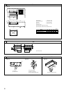
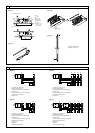
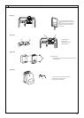
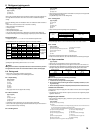
A Signal receiving unit external
B Center of Switch box
C Switch box
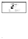
D Installation pitch
E 6.5 mm (1/4 inch)
F 70 mm (2 - 3/4 inch)
G 83.5 ± 0.4 mm (3 - 9/32 inch)
H Protrusion (pillar, etc)
[Fig. 8-9]
A
B
C
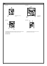
A Remote controller wire
B Hole (drill a hole on the ceiling to pass the remote controller wire.)
C Signal Receiving Unit
Ceiling cassette type, Ceiling concealed type
[Fig. 8-10]
A
B
C
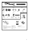
A Fix tightly with tape.
B Remote controller wire
C Order wire
Indoor unit
[Fig. 8-8]
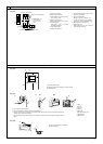
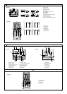
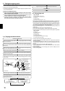
[Fig. 8-11]
H
J
I
When using the switch box
When installing directly on the wall
A 150 mm (5 - 15/16 inch)
B Remote controller wire
C Wiring pipe
D Locknut
H Seal around here with putty
I Remote controller wire
J Seal around here with putty
E Bushing
F Switch box
G Seal around here with putty
C
D
B
F
E
G
A
Wall
8
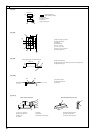
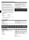
8.4
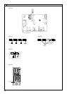
IC
OC(00)
CN90
TB1
TB4
1
D
C
A
B
Standard 1:1
[Fig. 8-7]
A Outdoor unit
B Refrigerant address
C Indoor unit
D Signal receiving unit
Indoor/outdoor wiring
Signal receiving unit wiring
00b_KB79U749H01_Illust.p65 2011.10.26, 4:52 PM8