


20
8. Electrical work
2) How To Install
[Fig. 8-8] (P.8) to [Fig. 8-15] (P.9)
1. Common items for “Installation on the ceiling” and “Installation on the switch
box or on the wall”
[Fig. 8-8] (P.8)
A Signal receiving unit external E 6.5 mm (1/4 inch)
B Center of Switch box F 70 mm (2 - 3/4 inch)
C Switch box G83.5 ± 0.4 mm (3 - 9/32 inch)
D Installation pitch H Protrusion (pillar, etc)
[Fig. 8-9] (P.8)
A Remote controller wire
B Hole (drill a hole on the ceiling to pass the remote controller wire.)
C Signal Receiving Unit
(1)Select the installation site.
The following must be observed.
1 Connect the signal receiving unit to the indoor unit with the supplied remote
controller wire. Note that the length of the remote controller wire is 5 m (16 ft).
Install the remote controller within the reach of the remote controller wire.
2 When installing on either the switch box or the wall, allow space around the
Signal Receiving Unit as shown in the figure in [Fig. 8-8].
3 When installing the Signal Receiving Unit to the switch box, the Signal Re-
ceiving Unit slipped downward for 6.5 mm (1/4 inch) as right illustrated.
4 Parts which must be supplied on site.
Switch box for one unit
Thin-copper wiring pipe
Lock nut and bushing
5 The thickness of the ceiling to which the remote controller is installed must be
between 9 mm (3/8 inch) and 25 mm (1 inch).
6 Install the unit on the ceiling or on the wall where the signal can be received
from the wireless remote controller.
The area where the signal from the wireless remote controller can be re-
ceived is 45 ° and 7 m (22 ft) away from the front of the signal receiving unit.
7 Install the signal receiving unit to the position depending on the indoor unit
model.
8 Connect the remote controller wire securely to the order wire. To pass the
remote controller wire through the conduit, follow the procedure as shown in
[Fig. 8-10].
[Fig. 8-10] (P.8)
A Fix tightly with tape. C Order wire
B Remote controller wire
Note:
• The point where the remote controller wire is connected differs depending
on the indoor unit model.
Take into account that the remote controller wire cannot be extended when
selecting the installation site.
• lf the Signal Receiving Unit is installed near a fluorescent lamp specially
inverter type,signal interception may occur.
Be careful for installing the Signal Receiving Unit or replacing the lamp.
(2)Use the remote controller wire to connect it to the connector (CN90) on the
controller circuit board on the indoor unit.
(3)Seal the Signal Receiving Unit cord lead-in hole with putty in order to pre-
vent the possible entry of dew, water droplets, cockroaches, other insects,
etc.
[Fig. 8-11] (P.8)
A 150 mm (5 - 15/16 inch)
B Remote controller wire
C Wiring pipe
D Locknut
E Bushing
F Switch box
G Seal around here with putty
• When installing on the switch box, seal the connections between the switch
box and wiring pipe with putty.
[Fig. 8-11] (P.8)
H Seal around here with putty
I Remote controller wire
J Seal around here with putty
• When opening a hole using a drill for Signal Receiving Unit wire (or taking the
wire out of the back of the Signal Receiving Unit), seal that hole with putty.
• When routing the wire via the portion cut off from the upper case, equally seal
that portion with putty.
(4)Install the remote control wire to the terminal block. [Fig. 8-12] (P.9)
(5) Installing hole when the Signal Receiving Unit is installed on the wall direct.
[Fig. 8-13] (P.9)
• Cut the thin-wall portion inside the bottom case (oblique section) by a knife or a
nipper.
• Take out the connected remote controller wire to the terminal brock through
this space.
(6) Install the lower case on the switch box or directly on the wall. [Fig. 8-14] (P.9)
Mounting the cover [Fig. 8-15] (P.9)
Caution:
• Insert the cover securely until the clicking sound is made. If not doing so, the
cover may fall.
8.4.2. Signal Receiving Unit
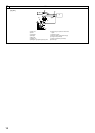
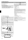
1) Sample system connection
[Fig. 8-7] (P.8)
Only the wiring from the signal receiving unit and between the remote controllers is
shown in [Fig. 8-7]. The wiring differs depending on the unit to be connected or the
system to be used.
For details on restrictions, refer to the installation manual or the service handbook
that came with the unit.
1. Connecting to Mr. SLIM air conditioner
(1)Standard 1:1
1 Connecting the signal receiving unit
Connect the signal receiving unit to the CN90 (Connect to the wireless re-
mote controller board) on the indoor unit using the supplied remote controller
wire. Connect the signal receiving units to all the indoor units.
2. Setting example
(1)To use the units in the same room
[Fig. 8-17] (P.10)
1 Separate setting
Assign a different pair number to each indoor unit to operate each indoor unit
by its own wireless remote controller.
[Fig. 8-18] (P.10)
2 Single setting
Assign the same pair number to all the indoor units to operate all the indoor
units by a single wireless remote controller.
[Fig. 8-19] (P.10)
(2)To use the units in different rooms
Assign the same pair number to the wireless remote controller as that of the
indoor unit. (Leave the setting as it is at purchase.)
2) Setting the Model No.
[Fig. 8-20] (P.10)
1 Insert batteries.
2 Press the SET button with something sharp at the end.
MODEL SELECT
blinke and Model No. lighted.
3 Press the temp
button to set the Model No.
4 Press the SET button with something sharp at the end.
MODEL SELECT
and Model No. are lighted for three seconds, then turned off.
8.4.3. Setting
1) Setting the pair number switch
[Fig. 8-16] (P.10)
1. Setting method
Assign the same pair number to the wireless remote controller as that of the indoor
unit. If not doing so, the remote controller cannot be operated. Refer to the instal-
lation manual that came with the wireless remote controller for how to set pair
numbers of wireless remote controllers.
Position of daisy wire on the controller circuit board on the indoor unit.
Controller circuit board on the indoor unit (reference) [Fig. 8-16] (P.10)
A CN90: Connector for remote controller wire connection
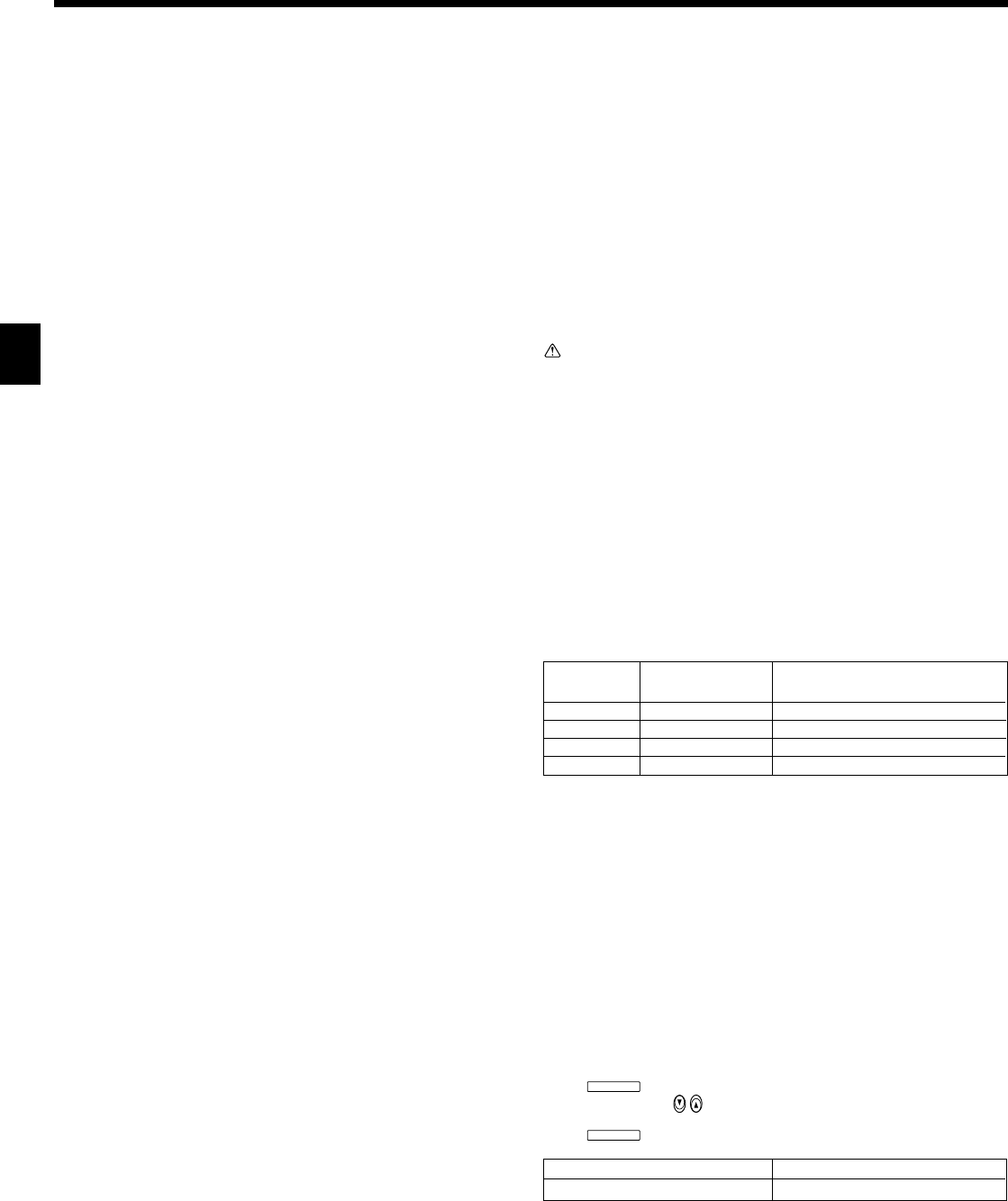
For pair number settings, the following 4 patters (A-D) are available.
Pair number
setting pattern
Pair number on
remote controller side
Indoor controller circuit board side Point
where the daisy wire is disconnected
A
B
C
D
0
1
2
3~9
Not disconnected
J41 disconnected
J42 disconnected
J41 and J42 disconnected
Indoor Unit Model
A Model No.
PEAD
026
01_KB79U749H01_GB.p65 2011.10.26, 4:49 PM20