


7
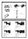
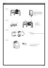
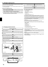
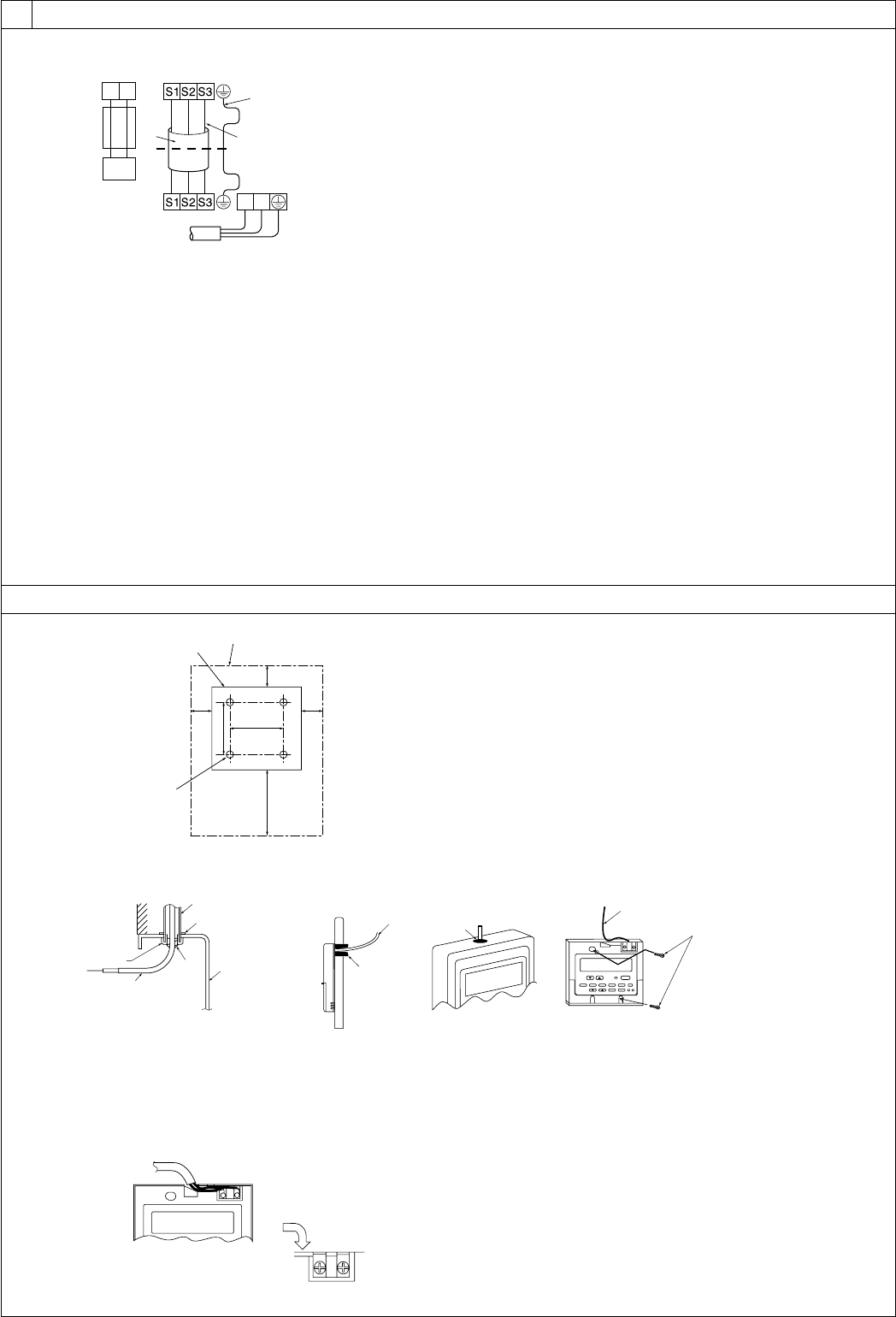
A For installation in the switch box:
B For direct installation on the wall select one of the following:
• Prepare a hole through the wall to pass the remote controller cord (in order to run the remote controller cord from
the back), then seal the hole with putty.
• Run the remote controller cord through the cut-out upper case, then seal the cut-out notch with putty similarly as
above.
C Wall
D Conduit
E Lock nut
F Bushing
G Switch box
H Remote controller cord
I Seal with putty
J Wood screw
F
A
H
C
D
E
G
I
I
I
H
B
J
H
B-1. B-2.
[Fig. 8-5]
8
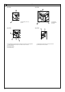
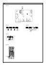
A
AB TB6
B
A To the terminal block on the indoor unit
B TB6 (No polarity)
[Fig. 8-6]
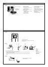
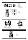
8.2
30
46
30
30120
83.5
A
B
C
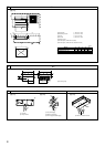
A Remote controller profile
B Required clearances surrounding the remote controller
C Installation pitch
[Fig. 8-4]
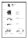
[Fig. 8-3]
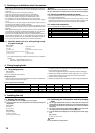
A Indoor terminal block
B Earth wire (green/yellow)
C Indoor/outdoor unit connecting wire 3-
core 1.5 mm
2
or more
D Outdoor terminal block
E Power supply cord : 2.0 mm
2
or more
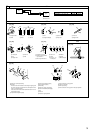
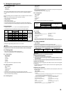
1 Connecting cable
Cable 3-core 1.5 mm
2
, in conformity
with Design 245 IEC 57.
2 Indoor terminal block
3 Outdoor terminal block
A Indoor terminal block
4 Always install an earth wire (1-core 1.5 mm
2
)
longer than other cables
5 Remote controller cable
Wire No × size (mm
2
) : Cable 2C × 0.3
This wire accessory of remote controller
(wire length : 10m, non-polar. Max. 500m)
6 Wired remote controller (option)
7 Power supply cord
Cable 3-core 2.0 mm
2
or more, in conform-
ity with Design 245 IEC 57.
12
6
5
2
4
3
7
L
N
1
C Indoor/outdoor unit
connecting wire
3-core 1.5 mm
2
or
more
D Outdoor terminal block
B Earth wire (green/yellow)
E Power supply cord : 2.0 mm
2
or more
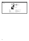
8.3
00b_KB79U749H01_Illust.p65 2011.10.26, 4:52 PM7