


19
8. Electrical work
8.2. Indoor wire connection
Work procedure
1.Remove 2 screws to detach the electric component cover.
2.Route each cable through the wiring intake into the electric component box. (Pro-
cure power cable and in-out connecting cable locally and use remote control cable
supplied with the unit.)
3.Securely connect the power cable and the in-out connecting cable and the remote
control cable to the terminal blocks.
4.Secure the cables with clamps inside the electric component box.
5.Attach the electric component cover as it was.
• Fix power supply cable and indoor/outdoor cable to control box by using buffer
bushing for tensile force. (PG connection or the like.)
Warning:
• Attach the electrical part cover securely. If it is attached incorrectly, it could
result in a fire, electric shock due to dust, water, etc.
• Use the specified indoor/outdoor unit connecting wire to connect the indoor
and outdoor units and fix the wire to the terminal block securely so that no
stress is applied to the connecting section of the terminal block. Incomplete
connection or fixing of the wire could result in a fire.
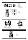
[Fig. 8-2-1] (P.6)
A Screw holding cover (1pc)
B Cover
[Fig. 8-2-2] (P.6)
C Terminal box
D Knockout hole
E Remove
[Fig. 8-2-3] (P.6)
F Use PG bushing to keep the weight of the cable and external force from being applied to the
power supply terminal connector. Use a cable tie to secure the cable.
G Power source wiring
H Use ordinary bushing
I Transmission wiring
[Fig. 8-2-4] (P.6)
J Terminal block for power source and indoor transmission
K Terminal block for remote controller
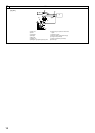
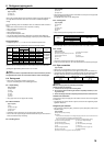
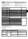
[Fig. 8-3] (P.7)
A Indoor terminal block
B Earth wire (green/yellow)
C Indoor/outdoor unit connecting wire 3-core 1.5 mm
2
or more
D Outdoor terminal block
E Power supply cord : 2.0 mm
2
or more
1 Connecting cable
Cable 3-core 1.5 mm
2
, in conformity with Design 245 IEC 57.
2 Indoor terminal block
3 Outdoor terminal block
4 Always install an earth wire (1-core 1.5 mm
2
) longer than other cables
5 Remote controller cable
Wire No × size (mm
2
) : Cable 2C × 0.3
This wire accessory of remote controller
(wire length : 10 m, non-polar. Max. 500 m)
6 Wired remote controller (option)
7 Power supply cord
Cable 3-core 2.0 mm
2
or more, in conformity with Design 245 IEC 57.
• Perform wiring as shown in [Fig. 8-3] (P.7). (Procure the cable locally.)
Make sure to use cables of the correct polarity only.
• Connect the terminal blocks as shown in [Fig. 8-3] (P.7).
Caution:
• Use care not to make mis-wiring.
• Firmly tighten the terminal screws to prevent them from loosening.
• After tightening, pull the wires lightly to confirm that they do not move.
8.3. Remote controller (wired remote controller (option))
8.3.1. For wired remote controller
1) Installing procedures
(1)Select an installing position for the remote controller.
The temperature sensors are located on both remote controller and indoor unit.
Procure the following parts locally:
Two piece switch box
Thin copper conduit tube
Lock nuts and bushings
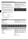
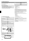
[Fig. 8-4] (P.7)
A Remote controller profile
B Required clearances surrounding the remote controller
C Installation pitch
(2) Seal the service entrance for the remote controller cord with putty to prevent pos-
sible invasion of dew drops, water, cockroaches or worms.
[Fig. 8-5] (P.7)
A For installation in the switch box:
B For direct installation on the wall select one of the following:
• Prepare a hole through the wall to pass the remote controller cord (in order to run the remote
controller cord from the back), then seal the hole with putty.
• Run the remote controller cord through the cut-out upper case, then seal the cut-out notch
with putty similarly as above.
C Wall G Switch box
D Conduit H Remote controller cord
E Lock nut I Seal with putty
F Bushing J Wood screw
B-1. To lead the remote controller cord from the back of the controller:
B-2. To run the remote controller cord through the upper portion:
(3)For direct installation on the wall
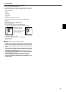
2) Connecting procedures
1 Connect the remote controller cord to the terminal block.
[Fig. 8-6] (P.7)
A To the terminal block on the indoor unit
B TB6 (No polarity)
2 Set the dip switch No.1 shown below when using two remote controller’s for the
same group.
3) Function selection of remote controller
If two remote controllers are connected, set one to “Main” and the other to “Sub”. For
setting procedures, refer to “Function selection of remote controller” in the operation
manual for the indoor unit.
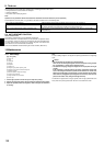
8.4. Remote controller (wireless remote controller (op-
tion))
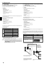
8.4.1. For wireless remote controller (option)
1) Installation area
• Area in which the remote controller is not exposed to direct sunshine.
• Area in which there is no near by heating source.
• Area in which the remote controller is not exposed to cold (or hot) winds.
• Area in which the remote controller can be operated easily.
• Area in which the remote controller is beyond the reach of children.
* The signal can travel up to approximately 7 meters (in a streight line) within 45 degrees to
both right and left of the center line of the receiver.
01_KB79U749H01_GB.p65 2011.10.26, 4:49 PM19