


16
6. Refrigerant piping work
6.4. Purging procedures leak test
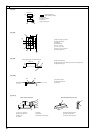
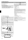
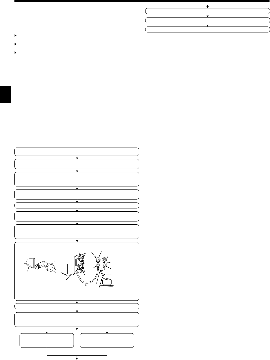
PURGING PROCEDURES
Connect the refrigerant pipes (both the liquid and gas pipes) between the indoor
and the outdoor units.
Remove the service port cap of the stop valve on the side of the outdoor unit gas pipe.
(The stop valve will not work in its initial state fresh out of the factory (totally closed
with cap on).)
Connect the gage manifold valve and the vacuum pump to the service port of the
stop valve on the gas pipe side of the outdoor unit.
Run the vacuum pump. (Vacuumize for more than 15 minutes.)
Check the vacuum with the gage manifold valve, then close the gage manifold valve,
and stop the vacuum pump.
Leave it as is for one or two minutes. Make sure the pointer of the gage manifold
valve remains in the same position. Confirm that the pressure gage show -0.101MPa
(-760 mmHg).
Pipe length :
7 m maximum
No gas charge is needed.
Pipe length exceeding 7 m
Charge the prescribed
amount of gas.
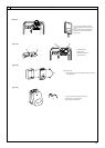
Remove the gage manifold valve quickly from the service port of the stop valve.
After refrigerant pipes are connected and evacuated, fully open all stop valves on
gas and liquid pipe sides.
Operating without fully opening lowers the performance and causes trouble.
Tighten the cap to the service port to obtain the initial status.
Retighten the cap
Leak test
1.Remove and discard the rubber bung which is inserted in the end of the unit piping.
2.Flare the end of the site refrigerant piping.
3.Pull out the thermal insulation on the site refrigerant piping and replace the insula-
tion in its original position.
Cautions On Refrigerant Piping
Be sure to use non-oxidative brazing for brazing to ensure that no foreign
matter or moisture enter into the pipe.
Be sure to apply refrigerating machine oil over the flare connection seating
surface and tighten the connection using a double spanner.
Provide a metal brace to support the refrigerant pipe so that no load is
imparted to the indoor unit end pipe. This metal brace should be provided
50 cm away from the indoor unit’s flare connection.
*Close
*Open
Hexagonal wrench
Stop valve
*4 to 5 turns
Stop valve
(or the vacuum
pump with the
function to
prevent the back
flow)
Gauge manifold
valve (for R410A)
Pressure gauge
(for R410A)
Compound pressure
gauge (for R410A)
-0.101MPa
(-760 mmHg)
Handle
Low
Handle High
Window
Charge hose
(for R410A)
Vacuum
pump
Adapter for
preventing
the back flow
Charge hose
(for R410A)
Service port
Stop
valve
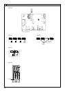
6.5. Drain piping work
[Fig. 6-10] (P.4)
A Downward slope 1/100 or more
B Connection dia. R1 external thread
C Indoor unit
D Collective piping
E Maximize this length to approx. 10 cm
• Ensure that the drain piping is downward (pitch of more than 1/100) to the out-
door (discharge) side. Do not provide any trap or irregularity on the way. (1)
• Ensure that any cross-wise drain piping is less than 20 m (excluding the differ-
ence of elevation). If the drain piping is long, provide metal braces to prevent it
from waving. Never provide any air vent pipe. Otherwise drain may be ejected.
• Use a hard vinyl chloride pipe O.D. ø32 for drain piping.
• Ensure that collected pipes are 10 cm lower than the unit body’s drain port as
shown in 2.
• Do not provide any odor trap at the drain discharge port.
• Put the end of the drain piping in a position where no odor is generated.
•
Do not put the end of the drain piping in any drain where ionic gases are generated.
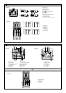
[Fig. 6-11] (P.4)
A Indoor unit
B Tie band (accessory)
C Band fixing part
D Insertion margin
E Drain socket (accessory)
F Drain pipe (O.D. ø32 PVC TUBE, field supply)
G Insulating material (field supply)
1.Insert the drain socket (accessory) into the drain port.
(The drain socket must not be bent more than 45° to prevent the socket from
breaking or clogging.)
The connecting part between the indoor unit and the drain socket may be dis-
connected at the maintenance. Fix the part with the accessory band, not be
adhered.
2.Attach the drain pipe (O.D. ø32 PVC TUBE, field supply).
(Attach the pipe with glue for the hard vinyl chloride pipe, and fix it with the band
(small, accessory).)
3.Perform insulation work on the drain pipe (O.D. ø32 PVC TUBE) and on the
socket (including elbow).
01_KB79U749H01_GB.p65 2011.10.26, 4:49 PM16