52
53
54
55
56
57
58
59
60
61
62
63
64
65
66
67
68
69
70
71
72
73
74
75
76
77
78
79
80
81
82
83
84
85
86
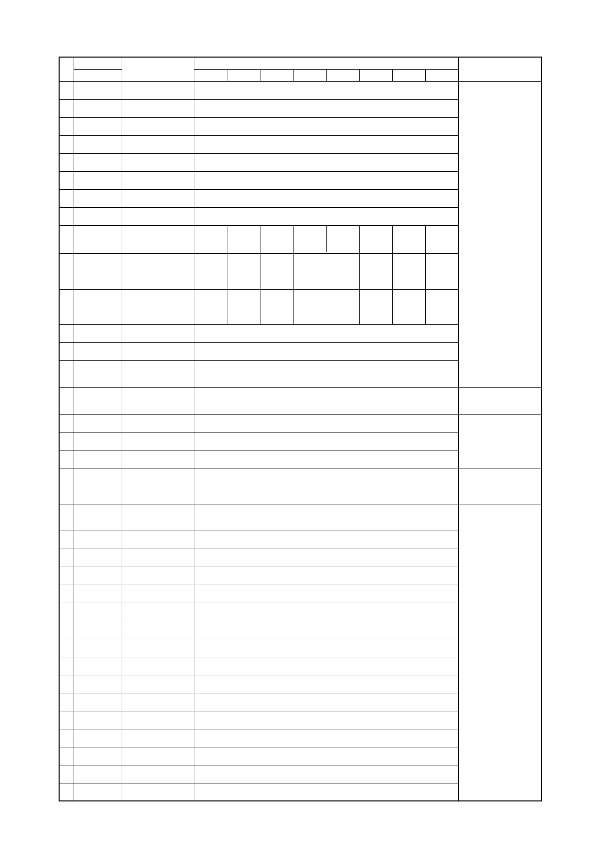
0010110000
1010110000
0110110000
1110110000
0001110000
1001110000
0101110000
1101110000
00111100
10111100
01111100
11111100
00000010
10000010
01000010
11000010
00100010
10100010
01100010
11100010
00010010
10010010
01010010
11010010
00110010
10110010
01110010
11110010
00001010
10001010
01001010
11001010
00101010
10101010
01101010
∆ Hz
–
Low
-3 deg.
or less
Low
-3 deg.
or less
No SW1 Item Display Remarks
12345678910 LD1 LD2 LD3 LD4 LD5 LD6 LD7 LD8
THHS Data
HPS Data
TH7 Data
TH8 Data
Accumulator Level
Change in Hz AK
Difference from
target TC
Difference from
target ET
Target TC
Target ET
Temporary
requency
Compressor
output frequency
AK
SLEV
LEV1
Fan controller
output value
DC buss current
OC address
IC1 address
IC2 address
IC3 address
IC4 address
IC5 address
IC6 address
IC7 address
IC8 address
IC9 address
IC10 address
IC11 address
IC12 address
IC13 address
∆ Hz
0
Low
-3 ~ -2
deg.
Low
-3 ~ -2
deg.
∆ Hz
+
Low
-2 ~ -1
deg.
Low
-2 ~ -1
deg.
–– ∆ AK
+
High 3
deg. or
more
High 3
deg. or
more
∆ AK
0
High
2~3
deg.
High
2~3
deg.
∆ AK
–
High
1~2
deg.
High
1~2
deg.
-99.9 ~ 999.9
↑
↑
↑
0~9 (“AL=” is also displayed)
E
✻
Actual frequency out-
put from inverter
Display fan controller
output value used for
control.
Stable region
Stable region
-99.9 ~ 999.9
↑
0 ~ 9999
↑
↑
↑
↑
0000 ~ 9999
-99.9 ~ 999.9
0000 ~ 9999
↑
↑
↑
↑
↑
↑
↑
↑
↑
↑
↑
↑
0000 ~ 9999
-
85
-


