


1
2
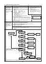
Despite pressing of
remote controller
switch, operation
does not start with no
electronic sound.
(No powering signal
appears.)
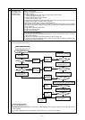
At about 10 seconds
after turning remote
controller operation
switch ON, the
display distinguishes
and the operation
stops.
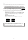
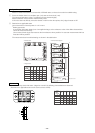
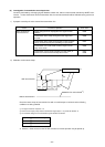
1) M-NET transmission power source is not supplied
from outdoor unit.
1Main power source of outdoor unit is not connected.
2Slipping off of connector on outdoor unit circuit
board
Main board : CNS1, CNVCC3
INV board : CNDC2, CNVCC2, CNL2
G/A board : CNDC1
3
Faulty power source circuit of outdoor unit
• Faulty INV board,
• Blown fuse (F01 on G/A board)
• Broken diode stack
• Broken resistor (R1) for rush current protection
2) Short circuit of transmission line
3) Erroneous wiring of M-NET transmission line at outdoor unit
1Transmission line disconnection or slipping off from terminal
block
2Erroneous connection of indoor/outdoor transmission line to
TB7
4) Slipping off of transmission wiring at remote controller
5) Faulty remote controller
The cause of 2) and 3) is dis-
played with self-diagnosis
LED for 7102 error.
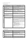
1) Power source is not fed to indoor unit from transformer.
1Main power source of indoor unit is not turned on.
2Slipping off of connector (CND, CNT, CN3T) on indoor controller board
3Blown fuse on indoor controller board
4
5
Faulty or disconnected transformer of indoor unit
Faulty indoor controller board
3) Faulty outdoor control circuit board or being out of control
As normal transmission is failed between indoor and outdoor units, outdoor unit model can not be
recognized.
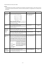
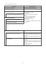
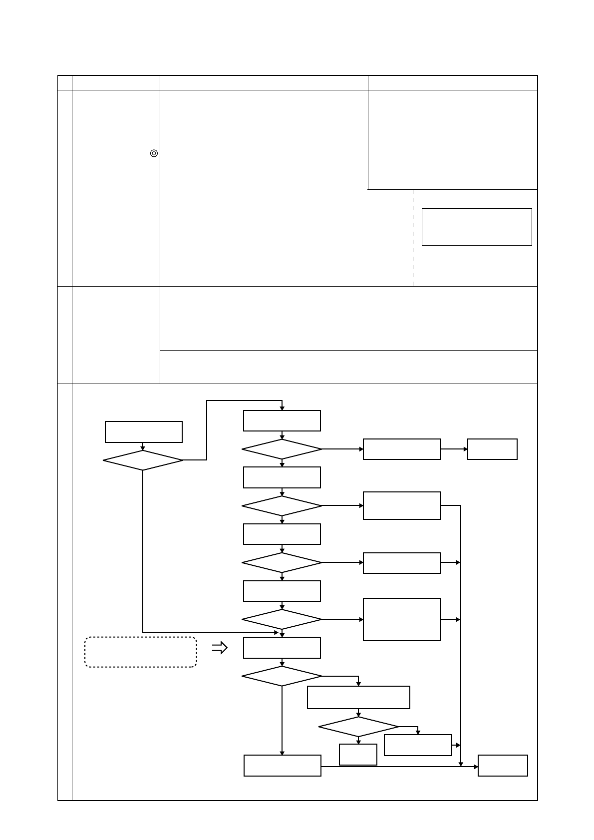
Checking method & countermeasure
Symptom Cause Checking method & countermeasure
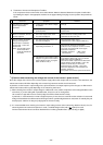
(5) Trouble and remedy of remote controller
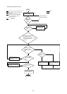
Extinguishing or
unable to confirm
Check indoor LED1
Lighting?
Lighting
Check fuse on circuit
board
Blown?
Check connector slip-
ping off
(CND, CNT, CN3T)
Slipped off?
Check transformer
resistance value
Within rated?
Check self-diagnosis
function of outdoor unit
Check for the change of LED
display by operating dip switch
SW1 for self-diagnosis.
Changed?
Check main power source
of power source wiring.
Apply power
source again.
Check 220V circuit for
short circuit and ground
fault.
Improper connector
connection
Changed?
Casual
trouble
Repair
faulty point.
Faulty outdoor unit
control circuit board
Faulty indoor
controller board
Check self-diagnosis function
after powering outdoor unit again.
Check indoor unit
power source terminal
block voltage
NO
YES
YES
✻
1
NO
NO
YES
NO
NO
YES
YES
YES
NO
Check cause of trans-
former disconnection.
•Ground fault on circuit
board
•Ground fault on
sensor, LEV
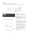
208~230V?
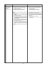
✻
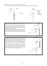
1 Check the transformer in accordance with the “TROUBLE SHOOTING” in the indoor unit’s service handbook.
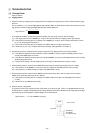
a) Check transmission terminal block of re-
mote controller for voltage.
i) In case of 17 ~ 30V
→ Faulty network remote controller
ii) In case of less than 17V
→ See “Transmission Power Circuit
(30V) Check Procedure” on Page 54.
-
50
-