


6
7
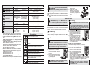
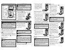
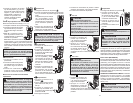
Resistance
1. Set the Dial to position.
2. Connect the red test lead to the
V terminal and the black test
lead to the COM terminal.
Confi rm “OL” is indicated on
the display, and then short-
circuit the tips of test leads to
make the indication zero.
3. Connect the test leads to the
both ends of the resistor under test.
4. The reading is displayed.
CAUTION After shorting the test leads,
the displayed value may not be zero due to the
resistance of test leads themselves.
Capacitance
1. Set the Dial to
position.
2. Use the Range button to se-
lect either 100F or 1000F.
3. Connect the red test lead
to the V terminal and the
black test lead to the COM
terminal.
4. Discharge capacitor.
5. Connect the test leads to the both ends of the
capacitor under test.
6. The reading is displayed.
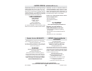
AC Current
DANGER To reduce the risk of
electric shock for Resistance, Continuity,
and Capacitance measurements, never use
the DMM on an energized circuit. Make sure a
capacitor is fully discharged before touching
or attempting to make a measurement.
Do not use with the Battery Cover removed.
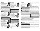
Hz Frequency
1. Set the Dial to Hz position.
2. Connect the red test lead to the
V terminal and the black test
lead to the COM terminal.
3. Connect the test leads to the
circuit under test. The reading
is displayed.
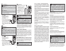
Resistance/Continuity/Capacitance
Measurements
DANGER To avoid electrical shock:
Never make measurement on a circuit in
which voltage over AC600V exists. Do not use
with the Battery Cover removed. Keep fi ngers
behind the guards and away from test lead
tips during measurements.
DANGER To avoid electrical shock:
Never make measurement on a circuit in
which voltage over AC600V exists.
Do not use with the Battery Cover removed.
Keep fi ngers behind the guards and away
from test lead tips during measurements.
1. Set the Dial to position.
2. Connect the red test lead
to the A terminal and the
black test lead to the COM
terminal.
3. Turn circuit power off, dis-
connect the circuit, connect
the test leads in series
with the circuit under test,
and then turn circuit power on. The reading is
displayed.
DC Current
Continuity
1. Set the Dial to position.
2. Connect the red test lead to
the V terminal and the black
test lead to the COM termi-
nal.
Confi rm “OL” is indicated on
the display, and then short-
circuit the tips of test leads to
make the indication zero. A
buzzer will sound.
3. Connect the test leads to the
both ends of the conductor
under test. If the resistance
under test is 30 or less, the
buzzer will sound.
1. Set the Dial to
position.
2. Connect the red test lead
to the A terminal and the
black test lead to the COM
terminal.
3. Turn circuit power off, dis-
connect the circuit, connect
the test leads in series
with the circuit under test,
and then turn circuit power on. The reading is
displayed.
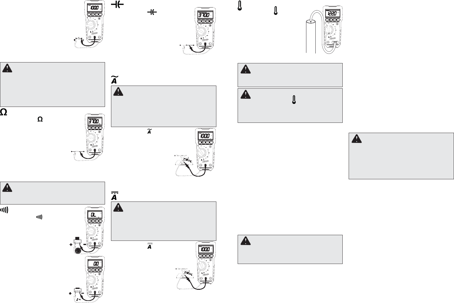
WARNING
Never connect the Temperature Probe to an
energized circuit.
CAUTION
When the dial is set to , OL should be dis-
played. If anything else is displayed, some-
thing may be wrong with the DMM. Stop using
the DMM immediately.
Temperature
1. Set the Dial to position.
2. Connect the K-type Tempera-
ture Probe to the input termi-
nal. The positive (+) side of
Probe should be connected
to V.
3. Contact the probe sensor to
the object under test.
4. The reading is displayed.
CAUTION
The Data Hold readings of maximum / mini-
mum are released when the DMM enters Sleep
Mode.
Press MIN/MAX to step through the minimum (MIN
displayed), maximum (MAX displayed), and pres-
ent readings (both MAX and MIN are displayed).
To pause MIN MAX recording without erasing
stored values, press HOLD button the HOLD is
displayed.
To resume MIN MAX recording, press HOLD but-
ton again.
To exit and erase stored readings, press MAN/MAX
button for two seconds or change the dial.
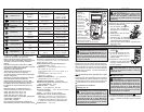
Range Button
The DMM has both Manual and Autorange modes.
In the Autorange mode, the DMM selects the range
with the best resolution, and in the Manual Range
mode, you override Autorange and select the range
yourself. When you turn the DMM on, it defaults
to Autorange and AUTO is displayed. To enter the
Manual Range mode, press RANGE button, AUTO
disappears. In the Manual Range mode, press
RANGE button to increment the range. After the
highest range, the Meter wraps to the lowest range.
To exit Manual Range, press RANGE button for two
seconds or change the dial. The Meter returns to
Autorange and AUTO is displayed.
CAUTION
Pressing the MIN/MAX button without apply-
ing voltage disables the Auto-ranging func-
tion and fi xes the Range to 6mV. Connect the
test leads to the circuit under test and press
the MIN/MAX button after an appropriate
range is selected by Auto-ranging function.
°F / °C
To switch between Fahrenheit or Celsius, press
the °F / °C button.
Sleep Mode
The DMM is automatically powered off in about 20
min after the last Rotary Dial or button operation. To
reset, rotate the Rotary Dial to OFF. If the display
is still blank when a new dial setting is selected,
replace the batteries.
The DMM does use battery power in sleep mode.
Be sure to switch the tool to OFF to conserve bat-
tery power.
Over-fl ow indication
Any time the input exceeds the measuring range
“OL” or “-OL” is displayed.
Accessory Bay
To install an accessory, slide it into the accessory
bay on the back of the DMM. Follow the instructions
supplied with the accessory
Using Bar Graph Display
The bar graph is like the needle on an analog me-
ter, it updates much faster than the digital display.
The number of segments indicates the measured
value and is relative to the full-scale value of the
selected range.
HOLD Button
Data Hold Function - Freezes the value on the dis-
play. Press the HOLD button to freeze the reading.
The reading will be held regardless of subsequent
variation in input. HOLD is displayed with the read-
ing. To exit Data Hold mode, press the HOLD button
again or change the dial.
SMART HOLD: The meter will beep continuously
and the display will fl ash if the measured signal is 50
counts larger than the display reading. (However,
it can not detect across the AC and DC Voltage/
Current).
MIN/MAX Button
The MIN MAX recording mode captures the mini-
mum and maximum input values. When a new high
or low is detected, the DMM beeps.
Put the DMM in the desired measurement function
and range, then press MIN/MAX button to enter
MIN MAX mode, and present readings and MAX
MIN are displayed.