


4
5
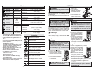
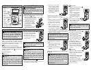
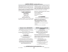
ASSEMBLY
2. Unscrew and remove
battery door.
3. Insert two (2) AA
batteries, according to
the polarity marked in
the battery compartment
4. Close the battery door
and
tighten screw securely.
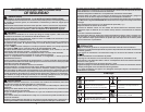
Symbology
Read Operator’s Manual
Double insulation
Risk of electric shock
Earth
Danger, Warning, or Caution -
Consult the operators manual for
additional safety information.
Battery compartment
European Conformity Mark
Underwriters Laboratories, Inc.,
United States and Canada
Cat III
Classifi cation of transient
overvoltages, based on nominal
line voltage to earth.
Fuse
Do not dispose of this product as
unsorted municipal waste.
WARNING
To avoid an electrical hazard,
turn the Rotary Dial to OFF and disconnect the
test leads before replacing batteries.
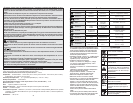
Dial Position Range Resolution Accuracy
Voltage AC
600mV/6V
60/600V
0.1mV/0.001V/
0.01V/0.1V
±(1.0% + 3 dgt) (45~500Hz)
±(2.0% + 3 dgt) (500~1000Hz)
Voltage DC 600mV/6/60/600V
0.1mV/0.001V/
0.01V/0.1V
±(0.5% + 2 dgt)
Lo-Z
Lo-Z
Low Input
Impedance
600V 0.1V ±(2.0% + 3 dgt) DC,AC : 45~500Hz
Hz
Hz
Hertz
99.99/999.9Hz
9.999/50.00kHz
0.01Hz/0.1Hz/
0.001kHz/0.01kHz
±(0.1% + 2 dgt)
Sensitivity: 10Vp-p
Resistance
600/6/60/600k
6M
40M
0.1/0.001k/0.01k/
0.1k/0.001M
±(1.0% + 5 dgt)
±(1.0% + 5 dgt)
0.01M ±(2.0% + 5 dgt)
Continuity
Cont Buzzer
0-600.0
Buzzer sounds at 30 or less
Capacitance
100F 0.1F
±(1.9% + 2 dgt)
1000F1F
Current AC
6A
10A
0.001A/0.01A ±(1.5% + 3 dgt) (45~500Hz)
Current DC
6A
10A
0.001A/0.01A ±(1.0% + 3 dgt)
Temperature
†
- 40ºC ~ 400ºC
-40ºF ~ 752ºF
0.1°C
0.2°F
±(1.0% + 10 dgt)
±(1.0% + 18 dgt)
Functions
†
Temperature Range, Resolution and Accuracy
are for the DMM. Temperature Probe may have
different specifi cations.
* These instruments are True-RMS sensing. All
voltage and current readings are True-RMS val-
ues.
* Input impedance: Voltage DC: 10M; Voltage AC:
10M // less than 100pF; Lo-z: 4k approximately
* Overload protection:
Voltage DC, voltage AC, Lo-Z Voltage and Herts:
AC/DC 720V for 10 second
Current DC & Current AC: AC/DC 20A for 10 sec.
Resistance, Continuity, Capacitance and Tem-
perature: AC/DC 600V for 10 second
* Maximum measurement time: 1 minute at 10A,
rest time 20 minutes minimum
* Minimum frquency measurement is 2Hz
* Minimum AC Current measurement is 0.040A
* For AC Voltage, AC Current and Lo-z:
Additional Accuracy by Crest Factor (C.F.): Add
1.0% for C.F. 1.4 ~ 2.0
Add 2.5% for C.F. 2.0 ~ 2.5
Add 4.0% for C.F. 2.5 ~ 3.0
Max. Crest Factor: 1.6 for 6600 ~ 5000 digits
2.0 for 5000 ~ 3000 digits
3.0 for 3000 ~ 0 digits
* Measurement accuracy of square wave and trun-
cated waveforms at 1kHz is unspecifi ed.
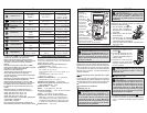
Loading/Changing the Batteries
Replace batteries when the Low Battery indicator
is displayed.
1. Turn Rotary Dial to OFF and disconnect the test
leads.
OPERATION
Before Use
Confi rm the Rotary Dial is set to the correct position,
the instrument is set to the correct measurement
mode, and the Data hold function is disabled. Oth-
erwise, desired measurement cannot be made.
LCD Backlight
The LCD backlight will turn off after about 10 min-
utes of inactivity. Press the backlight button to
turn the backlight on again.
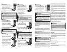
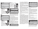
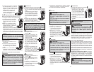
Making a Measurement
AC Voltage
DANGER To avoid electrical shock:
Never make measurement on a circuit in
which voltage over AC600V exists.
Do not use with the Battery Cover removed.
Keep fi ngers behind the guards and away
from test lead tips during measurements.
CAUTION Readings may fl uctuate or
be infl uenced in noisy environment.
1. Set the Dial to position.
2. Connect the red test lead
to the V terminal and the
black test lead to the COM
terminal.
3. Connect the test leads to the
circuit under test. The read-
ing is displayed.
1. Set the Dial to
position.
2. Connect the red test lead
to the V terminal and the
black test lead to the COM
terminal.
3. Connect the red test lead
to the positive (+) side
and black test leads to the
negative (-) side of the cir-
cuit under test. The reading
is displayed. A reversed connection is indicated
as a negative value.
Lo-Z Low Input Impedance
Automatic voltage detection (AC or DC).
1. Set the Dial to Lo-Z position.
2. Connect the red test lead
to the V terminal and the
black test lead to the COM
terminal.
3. AC: Connect the test leads
to the circuit under test. The
reading is displayed.
DC: Connect the red test lead
to the positive (+) side and
black test leads to the negative (-) side of the circuit
under test. The reading is displayed. A reversed
connection is indicated as a negative value.
DANGER To avoid electrical shock:
Never make measurement on a circuit in
which voltage over DC600V exists. Do not use
with the Battery Cover removed. Keep fi ngers
behind the guards and away from test lead
tips during measurements.
DC Voltage
WARNING Only use Milwaukee test
leads with the MILWAUKEE DMM. Inspect test
leads for continuity before each use. Do not
use if the readings are high or noisy.
CAUTION Do not use the DMM to measure
voltages in circuits that could be damaged
by the DMM’s low input impedance less than
approximately 4k.