


24
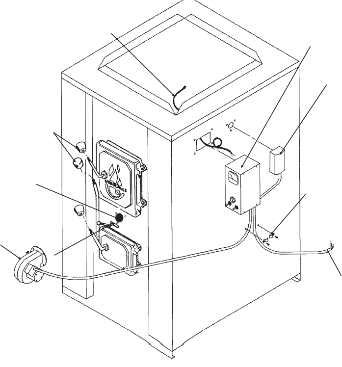
THERMOCOUPLE WIRE
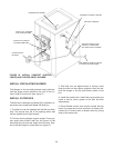
INSTALL ALL CONTROL
AND HANDLE KNOBS
KNOCKOUT IN DRAFT
CHANNEL REMOVED
FORCED DRAFT
BLOWER
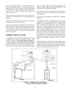
COMFORT CONTROL CENTER
FAN/LIMIT CONTROL
SECURE CONDUIT WITH
CONDUIT CLAMPS AND
#10 SHEET METAL SCREW
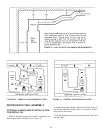
FIGURE 20 INSTALL COMFORT CONTROL
CENTER AND FORCED DRAFT BLOWER
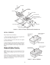
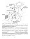
PRE-WIRED FLEXIBLE CONDUIT
TO CIRCULATING BLOWER
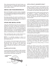
INSTALL CIRCULATING BLOWER
The flanges on the circulating blower simply slide be
-
hind the angle mounts welded to the rear of the fur
-
nace. Slide in from the top side, figure 21.
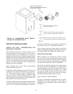
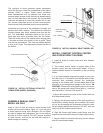
INSTALL FILTER BOX
The filter box is standard on Model 526. Installation in
-
structions are included with Model 526 filter box.
1. The filter box can be installed with the filter on either
side. The access door will fit the opening either side
and the handle should face forward.
2. Find two factory shipped support angles. Force sup
-
port angle sides without tabs into the groove of the
mounting strip on both rear sides of the furnace. Posi
-
tion at correct height to accept filter box, figure 21.
3. With filter box set against back of furnace, bend
down the tabs on the support angles so they lock be
-
hind the flanges of the top and bottom panels of the
box.
4. Install the access door. Install filter not supplied and
install a cold air return system to the filter box filter
side opening.
5. Route flexible conduit from comfort control through
hole in top panel and to box connector on blower con
-
nection box. Connect wires to blower motor by joining
wires of the same color.