


25
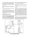
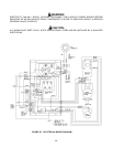
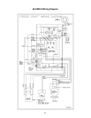
ELECTRICAL HOOKUP (FIGURE 22)
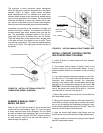
1. If you have an optional temperature gauge to monitor
heat exchanger temperature in your comfort control
center, then the thermocouple wires must be connected
to the gauge when installing the control. See figure 20.
IMPORTANT: Remove the wire ground clip from the ter
-
minals of the gauge and connect White wire to + termi
-
nal and Red wire to - terminal. See figure 22.
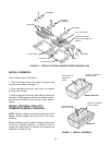
2. A prewired conduit is connected to the comfort con
-
trol center for the circulating blower. The opposite end is
to be connected in the junction box on the blower motor.
Connect like colored wires. Secure conduit to junction
box with box connector.
3. The comfort control is factory wired to the forced draft
motor (optional on Model 526). If you have the forced
draft, locate a wall thermostat in the desired location of
you house and run #18 thermostat wire (not furnished)
from this thermostat to R and G terminals of the trans
-
former in the comfort control. These connections have
been routed to a terminal strip on the outside of the
comfort control box for convenient connection.
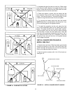
4. The circulating blower limit control is factory wired to
the comfort control center. Jumper removed, normal fan
limit control settings are 160°F ON, and 110°F OFF.
5. Route 110VAC power through conduit from your
power supply to the comfort control center box. Route
through box connector provided and connect hot (L
1
)to
BLACK, Neutral to WHITE and ground to GREEN as
shown on figure 22. You must provide a power discon
-
nect in the power supply line to your furnace which is
within sight of the Woodchuck and not more than 30
feet away. Your circuit breaker at the power supply may
meet these requirements.
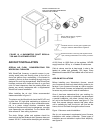
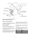
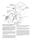
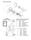
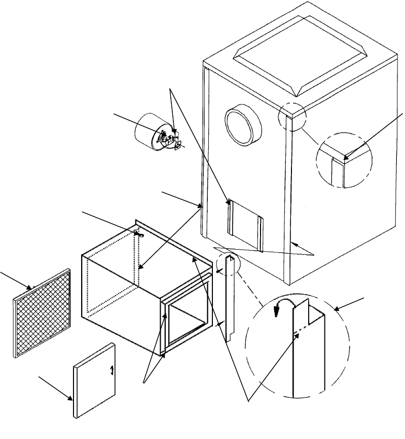
SLIDE FLANGES OF
CIRCULATING BLOWER
BEHIND ANGLES ON BACK
OF FURNACE
ELECTRICAL
CONNECTION BOX
FORCE FLANGE OF SUPPORT
ANGLE INTO GROOVE ON FURNACE
MOUNTING STRIP
ACCESS DOOR
HOLE FOR
CONDUIT
FILTER (NOT
SUPPLIED)
FILTER
ANGLES
BEND TABS ON SUPPORT ANGLE
OVER, BEHIND FLANGE ON FILTER
BOX, TOP & BOTTOM
SUPPORT ANGLE
GROOVE IN
FURNACE
MOUNTING STRIP,
BOTH SIDES
FIGURE 21 INSTALL CIRCULATING BLOWER AND FILTER