


23
The pyrolysis of wood produces certain substances
which will not burn unless the temperature in the firebox
reaches 1000°F or higher. Under normal conditions
these temperatures are not attained and these sub
-
stances simply escape up the chimney as wasted energy
and can form deposits in the chimney. By forcing these
unburned substances to come into contact with a cata
-
lyst, we can cause them to burn at much lower tempera
-
tures that are easily attainable during normal operation.
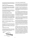
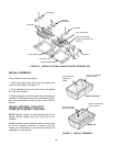
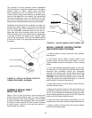
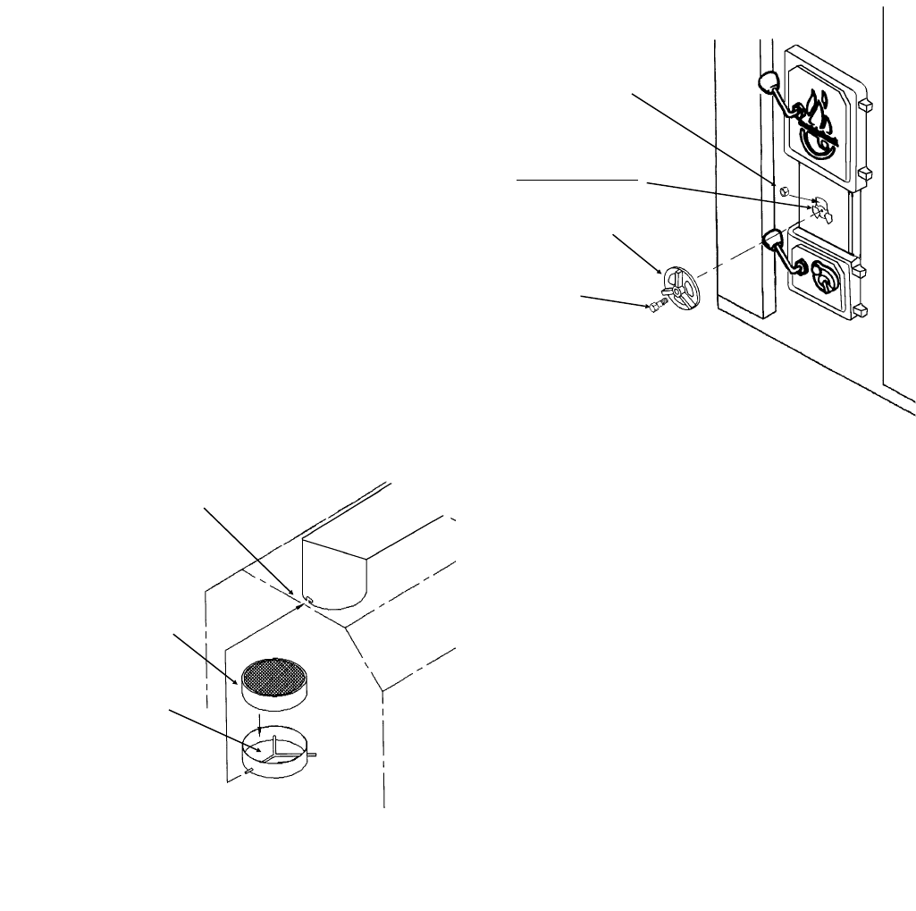
Installation and removal of the combustor is simple, the
element fits inside a retainer. The retainer fits inside the
furnace exhaust pipe which extends down into the fire
-
box. The assembled combustor slides up into the ex
-
haust pipe stub which protrudes down into the firebox.
There are three rods on the retainer which engage slots
in the pipe and then turn slightly to lock in place. These
rods are not symmetrical. Two rods are welded together
to form a 90° angle. This angle points toward the rear of
the firebox.
SLOTS IN EXHAUST PIPE
CATALYTIC ELEMENT
RODS ON RETAINER
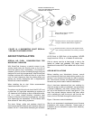
FIGURE 18 INSTALL OPTIONAL CATALYTIC
COMBUSTOR (MODEL 2900/4000)
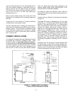
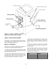
ASSEMBLE MANUAL DRAFT
MODEL 526 ONLY
Using a 1/4x1-1/2 bolt and locknut, mount manual draft
control onto the draft channel, figure 19. If you are going
to install optional forced draft, disregard. Do not tighten
too tight to damper draft adjustment, but not too loose to
let more air in than required. DO NOT remove knockout
on draft channel. Locknut can be held with wrench in
-
serted through air opening.
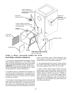
INSTALL COMFORT CONTROL CENTER
AND FORCED DRAFT BLOWER
1. Install all knobs to control levers and door handles.
See figure 20.
2. The comfort control center is factory wired to the
fan/limit control and the forced draft blower. It has a
prewired flexible conduit for connection to the circulating
blower.
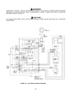
3. If you have optional temperature gauge on your con
-
trol, then strip ½" of insulation from the two leads of ther
-
mocouple wire protruding through the rectangular
opening on the furnace side. Connect these leads to the
terminals on the temperature gauge of the control. IM
-
PORTANT: Remove the wire ground clip from the termi
-
nals of the gauge and connect White wire to + terminal
and Red wire to - terminal. See figure 22.
4. Mount the control to the side of the furnace with four
#10 sheet metal screws.
5. Remove the knockout section of the draft channel on
model 526 by striking sharply with a hammer. Be careful
so you do not damage the mechanism inside the chan
-
nel and directly behind the knock-out. DO NOT allow the
knock-out to fall inside the draft channel.
6. Align the forced draft blower outlet flange over the
knockout and secure with three #10 sheet metal screws.
7. Secure conduit to furnace side using conduit clamps
and #10 sheet metal screws.
FIGURE 19 INSTALL MANUAL DRAFT-MODEL 526
1/4 LOCKNUT
DO NOT REMOVE
KNOCKOUT
MANUAL DRAFT
CONTROL
1/4x1-1/2 BOLT