


4
NOTE: DIAGRAMS & ILLUSTRATIONS NOT TO SCALE.
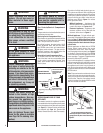
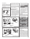
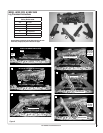
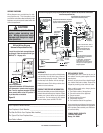
Figure 2
Sit and Honeywell Millivolt Gas Valve
Showing Piezo Igniter Location (Each Unit is
Equipped with Only One of these Gas Valves)
WARNING
These fireplaces are vented
heaters. Do not burn wood or
other material in these appli-
ances.
WARNING
This appliance is only for use
with the type of gas indicated on
the rating plate. This appliance
is not convertible for use with
other gases, unless a certifi ed
kit is used.
WARNING
Do not place clothing or other
fl ammable materials on or near
this appliance.
WARNING
Carbon monoxide poisoning:
early signs of carbon monoxide
poisoning are similar to the fl u
with headaches, dizziness and/or
nausea. If you have these signs,
obtain fresh air immediately. Turn
off the gas supply to the appliance
and have it serviced by a quali-
fi ed professional, as it may not
be operating correctly.
WARNING
Any safety guard or screen
removed for servicing the appli-
ance must be replaced prior to
operating the appliance.
WARNING
Children and adults should be
alerted to the hazards of high
surface temperatures. Use cau-
tion around the appliance to
avoid burns or clothing ignition.
Young children should be carefully
supervised when they are in the
same room as the appliance.
Note: An Optional Screen Heat
Guard for the glass is available
(see Page 16 for ordering infor-
mation).
Gas Controls/Control Compartment
Access
The gas controls can be found behind the control
compartment access door.
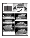
Removing Control Compartment Door:
Open the door by gently liftint it upward until the
hook catches on boths sides clear the locating
slots. Then pull door out to remove.
On millivolt systems, the piezo igniter, HI/LO
fl ame adjustment knob, and pilot and main
gas OFF/ON control knob are located below
the glass panel enclosure. The gas valve for
electronic systems is also located below the
glass enclosure panel. See Figure 1.
Reinstalling Control Compartment Door:
To reinstall, insert the hook catches on each
side of the door into the corresponding slots
in the control compartment opening, then
gently push forward and slide down until it
locks in place.
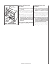
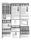
Figure 1
OPENING CONTROL
COMPARTMENT DOOR
Operation of millivolt and electronic gas con-
trol systems are different. Before lighting and
operating your appliance determine if you have
a millivolt or electronic appliance. Familiarize
yourself with the gas control valve that your
appliance uses. Refer to Figure 1 for access
to the gas control valve.
Millivolt Appliances - Appliances with
Millivolt systems will be fi tted with the gas
control valve shown in Figures 4 or 5.
Electronic Appliances - Appliances with
electronic systems will be fi tted with the
electronic valve shown in Figure 3.
Millivolt Appliances - To light millivolt appli-
ances refer to the detailed lighting instructions
found on Page 17 . Millivolt appliance lighting
instructions may also be found on the pull out
lighting instruction labels attached to the gas
control valve.
Millivolt appliances are fi tted with an OFF/ON
Rocker Switch located behind the control
compartment access door, below the appli-
ance front glass enclosure panel (see Figure 2
for location). Once the pilot is lit, the OFF/ON
rocker switch will control the appliance OFF/ON
burner operation. To operate: Toggle the switch
between its ON and OFF positions.
If your millivolt appliance is equipped with an
optional remote switch kit (wall switch, remote
control or wall thermostat) and the pilot is lit,
the appliance main burner may be turned on
and off using the optional switch. When using
an optional remote switch, turn off the standard
OFF/ON switch.
OPERATION AND CARE OF YOUR
APPLIANCE
The standard controls for appliance operation
are located behind the hinged drop-down panel
below the appliance front glass enclosure panel
(see Figure 1). Optional control switches are
also available (see Page 14 - Remote Wall
Switch, Remote Control or Wall Thermostat).
Note: To prevent excessive resistance in burner
circuit (which can cause burner operation prob-
lems), only one burner control switch should be
wired to valve. Therefore, if an optional control
switch is installed, the standard Off/On switch
and wires should be removed.
Control Valve
Lower Control
Compartment Door
SIT Gas Valve
Shown with control
compartment door
removed
Piezo Igniter
Honeywell
Gas Valve
Lift the Lower Control
Compartment Door
up and pull out to
remove.
Up
Out
Hook Catch