


12
NOTE: DIAGRAMS & ILLUSTRATIONS NOT TO SCALE.
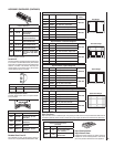
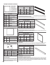
Main Burner Factory Air Shutter
Opening Setting - Inches (millimeter)
Model Natural
Gas
Propane
Gas
LMDVT-3328
1/16"
(1.58 mm)
1/4"
(6.35 mm)
LMDVR-3328
1/16"
(1.58 mm)
1/4"
(6.35 mm)
LMDV-3530
1/16"
(1.58 mm)
5/16"
(7.94 mm)
LMDV-4035
1/8"
(3.18mm)
3/8"
(9.53 mm)
Figure 12
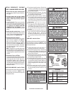
WARNING
Air shutter adjustment should
only be performed by a qualifi ed
professional service technician.
WARNING
Ensure front glass panel is in place
and sealed during adjustment.
CAUTION
The air shutter door and nearby
appliance surfaces are hot. Exer-
cise caution to avoid injury while
adjusting fl ame appearance.
CAUTION
Carbon will be produced if the air
shutter is closed too much. Any
damage due to carboning result-
ing from improperly setting the
air shutter is not covered under
the warranty.
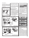
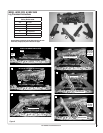
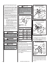
Burner Air Shutter Adjustment Procedure
1. Locate adjustment rod and adjust air shutter
to the standard setting as shown in Figure
12 (adjustment rod is located in the lower
control compartment). Note: Rotating the
adjustment rod clockwise decreases air and
counterclockwise increases air.
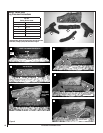
2. Light appliance (follow lighting procedure on
lighting label in control compartment or see
homeowners manual).
3. Allow the burner to operate for at least 15 min-
utes while observing the fl ame continuously
to ensure that the proper fl ame appearance
has been achieved (see Figures 10 or 11). If
the following conditions are present, adjust
accordingly.
• If flame appears weak or sooty, adjust
the air shutter, incrementally, to a more
open position until the proper fl ame
appearance is achieved.
• If fl ame stays lowered blue, adjust the
air shutter, incrementally, to a more
closed position until the proper fl ame
appearance is achieved.
4. Leave the control knob (off/pilot/on) in the
ON position and the burner OFF/ON switch
OFF (& remote switches, if applicable).
5. When satisfi ed that the burner fl ame ap-
pearance is normal, close the lower control
compartment door.
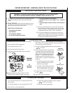
Burner Air Shutter Adjustment
Adjustment Rod Up
(Fully Open Position)
Air Shutter
Adjustment Rod Down
(minimum air opening
position)
Burner Tube
Adjustment Set-Screw
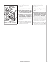
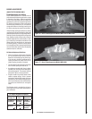
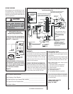
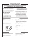
Electronic Appliance Checkout
To light the burner, refer to the lighting instruc-
tions on Page 18. Ensure the igniter lights the
pilot. The pilot fl ame should engulf the fl ame
sensor as shown in Figure 15.
With proper care and maintenance, your appli-
ance will provide many years of enjoyment. If
you should experience any problem, fi rst refer
to the troubleshooting guide in this manual.
If problem persists, contact your Lennox
distributor.
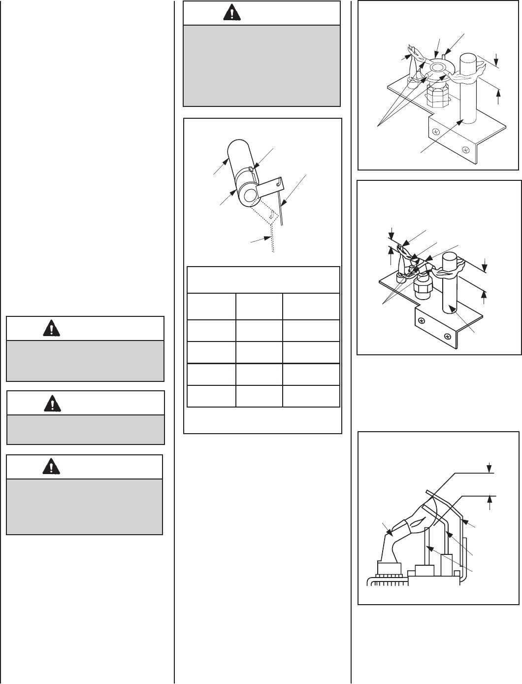
Figure 15
3/8" to 1/2"
(9 -13 mm)
Ground
Electrode
Flame Rod
Hot Surface
Igniter
Proper Flame
Adjustment
Pilot
Nozzels
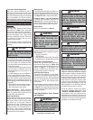
ELECTRONIC PILOT ASSEMBLY
Proper Pilot Flame Appearance
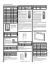
Figure 13
Thermocouple
Thermopile
Pilot
Nozzels
SIT MILLIVOLT PILOT ASSEMBLY
3/8" Min.
(9 mm)
Igniter Rod
Hood
Proper Pilot Flame Appearance
Figure 14
Proper Pilot Flame Appearance
Thermocouple
Thermopile
Pilot
Nozzels
3/8" Min.
(9 mm)
1/8" Min.
(3 mm)
Igniter Rod
Hood
HONEYWELL MILLIVOLT PILOT ASSEMBLY
Millivolt Appliance Checkout
The pilot fl ame should be steady, not lifting
or fl oating. Flame should be blue in color with
traces of orange at the outer edge.
The top 3/8" (10 mm) at the pilot generator
(thermopile) and the top 1/8" minimum (tip)
of the quick drop out thermocouple should be
engulfed in the pilot fl ame. The fl ame should
project 1" (25 mm) beyond the hood at all three
ports. See Figures 13 or 14.
To light the burner, refer to the lighting instruc-
tions on Page 17.