


3
NOTE: DIAGRAMS & ILLUSTRATIONS NOT TO SCALE.
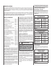
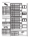
Burner Orifi ce Sizes
Elevation 0-4500 feet ( 0-1372 meters)
Model
Series
Natural
Gas
drill size
(inches)
Propane
Gas
drill size (inches)
LMDVT-3328
LMDVR-3328
#45 (.082")
*
39L6601 •
(.048")
*
99K78 •
LMDV-3530
#44 (.086")
*
60J8001 •
#55 (.052")
*
19L5201 •
LMDV-4035
#37 (.104")
*
24M1001 •
1/16"
(.0625")
*
21L0101 •
* Standard size installed at factory
• Part /Cat. Number
Table 7
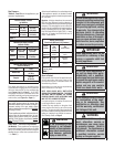
Inlet Gas Supply Pressure
(all models)
Fuel # Minimum Maximum
Natural Gas
5.0" WC
(1.24 kPa)
10.5" WC
(2.61 kPa)
Propane
11.0" WC
(2.74 kPa)
13.0" WC
(3.23 kPa)
Table 4
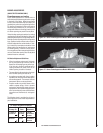
Burn-in Period
During the fi rst few fi res of this appliance there
will be some odor due to the curing of the
paint and burning off of lubricants used in the
manufacturing process.
Depending on your use, the burn-in period may
take a few hours or a few days.
KEEP YOUR HOUSE WELL VENTILATED
DURING THE CURING PROCESS. THE ODOR
AND HAZE EMITTED DURING THE CURING
PROCESS CAN BE QUITE NOTICEABLE AND
MAY SET OFF A SMOKE DETECTOR.
If an optional blower is installed, Do not turn it
on during the Burn-In period.
A white fi lm may develop on the glass front
during the fi rst few fi res as part of the curing
process. The glass should be kept clean during
the fi rst two weeks of use to prevent the fi lm from
baking on (making it very diffi cult to remove).
See Cleaning Glass on Page 6.
WARNING
Failure to comply with the instal-
lation and operating instructions
provided in this document will
result in an improperly installed
and operating appliance, voiding
its warranty. Any change to this
appliance and/or its operating
controls is dangerous. Improper
installation or use of this appli-
ance can cause serious injury or
death from fi re, burns, explosion
or carbon monoxide poisoning.
WARNING
Do not use these appliances if
any part has been under water.
Immediately call a qualifi ed,
professional service technician
to inspect the appliances and to
replace any parts of the control
system and any gas controls
which have been under water.
IMPORTANT
These appliances must not be
connected to a chimney or fl ue
serving a separate solid fuel
burning appliance.
WARNING
Do not attempt to alter or modify
the construction of the appli-
ance or its components. Any
modifi cation or alteration may
void the warranty, certifi cation
and listings of this unit.
These appliances and their individual shut-off
valves must be disconnected from the gas
supply piping system during any pressure
testing of that system at pressures greater
than 1/2 psig (3.5 kPa).
These appliances must be isolated from the
gas supply piping system (by closing their
individual manual shut-off valve) during any
pressure testing of the gas supply piping
system at test pressures equal to or less than
1/2 psig (3.5 kPa).
At the time of installation, it must be determined
if the appliance needs to be derated. Contact
your local gas supplier for deration requirements
for your area.
Deration - At higher elevations, the amount of
BTU fuel value delivered must be reduced by
either using gas that has been derated by the gas
company or by changing the burner orifi ce to a
smaller size as regulated by the local authorities
having jurisdiction and by the (USA) National
Fuel Gas Code NFPA 54 / ANSI Z223.1 - latest
edition or, in Canada, the CAN1-B149.1 and .2
codes - latest edition.
Gas Pressure -
Tables 4, 5 and 6 show the appliances' gas
pressure requirements.
Manifold Gas Supply Pressure
(millivolt models)
Fuel # Low High
Natural
Gas
(Lo) 2.2" WC
(.55 kPa)
(Hi) 3.5" WC
(.87 kPa)
Propane
(Lo) 6.3" WC
(1.57 kPa)
(Hi) 10.0" WC
(2.49 kPa)
Table 5
Manifold Gas Supply Pressure
(electronic models)
Fuel # Fixed
Natural Gas
3.5" WC
(.87 kPa)
Propane
10.0" WC
(2.49 kPa)
Table 6
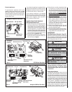
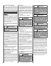
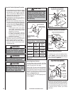
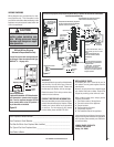
Test gauge connections are provided on the
front of the millivolt gas control valve, identifi ed
IN for the inlet and OUT for the manifold side
(see Figures 4 or 5 on Page 5 ). A 1/8" NPT
Test gauge connection is provided at the inlet
and outlet (manifold) ports on the electronic gas
control valve (see Figure 3 on Page 5 ).
Orifi ce Sizes - Sea Level to High Altitude
(All Models): These appliances are tested and
approved for installations at elevations of 0-4500
feet (0-1372 meters) above sea level using the
standard burner orifice sizes (marked with an
"*" in Table 7 ).
WARNING
If the information in this
manual is not followed
exactly, a fi re or explosion
may result causing prop-
erty damage, personal
injury or loss of life.
WARNING
Improper installation, adjust-
ment, alteration, service or
maintenance can cause injury
or property damage. Refer to
this manual. For assistance or
additional information consult
a qualifi ed installer, service
agency or the gas supplier.