Instructions for Installation (cont'd)
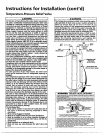
Temperature-Pressure Relief Valve
•,WARNING _, WARNING
At the time of manufacture this water heater was provid- The temperature-pressure relief valve must be manu-
ed with a combinationtemperature-pressuresrelief valve ally operated at least once a year. Caution should be
certified bya nationally recognizedtesting laboratory that taken to ensure that (1) no one is in front of or
maintains periodic inspectton of production of listed around the outlet of the temperature-pressuro relief
equipment or materials, as meeting the requirements for valve discharge line. and (2) the water manually dis-
Relief Valvesand Automatic Gas Shutoff Devicesfor Hot charged will not cause any bodily injury or property
Water Supply Systems. and the latest edition of ANSI damage because the water may be extremely hot.
Z21.22 and the code requirements of ASME. If replaced. If after manually operating the valve, it fails to com-
the valve must meet the requirements of localcodes,but
pletely reset and continues to release water, immedi-
not less than a combination temperature and pressure ateiy close the cold water inlet to the water heater.
relief valve certified as meeting the requirements for follow the draining instructions, and replace the
Relief Valvesand Automatic Gas Shutoff Devicesfor Hot temperature-pressure relief valve with a new one.
Water SupplySystems.ANSIZ21.22 by a nationally recog-
nizedtesting laboratory that maintainsperiodicinspection _ __
HOT COLD
of productionof listed equipmentor materials. )__T
The valve must be marked with a maximum set pressure _ " SHUT-OFF
not to exceedthe marked hydrostaticworking pressureof
the water heater (150 Ibs./sq.in.)and a dischargecapacity PIPE_ _ _ -- PIPE
not lessthan the water heater input rate as shown on the INSULATION _ INSULATION
model rating plate. (Electric heaters - watts divided by
1000x 3415 equal BTU/Hr.rate.)
Your local jurisdictional authority, while mandating the CONDUIT
useof a temperature-pressure relief valve complyingwith I ]
ANSI Z21.22 and ASME. may requirea valve model differ- _ /TEMPERATURE-PRESSURE
ent from the one furnished with the water heater. RELIEFVALVE
Compliancewith suchlocal requirements must foesatisfied
by the installer or end user of the water heater with a
locally prescribed temperature-pressure relief valve ¢-- DISCHARGEPIPE
installedin the designated opening in the water heater in _(Do notcapor plug)
placeof the factoryfurnished valve.
]
For safe operation of the water heater, the relief valve
must not be removed from it's designated opening or
plugged.
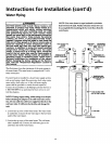
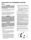
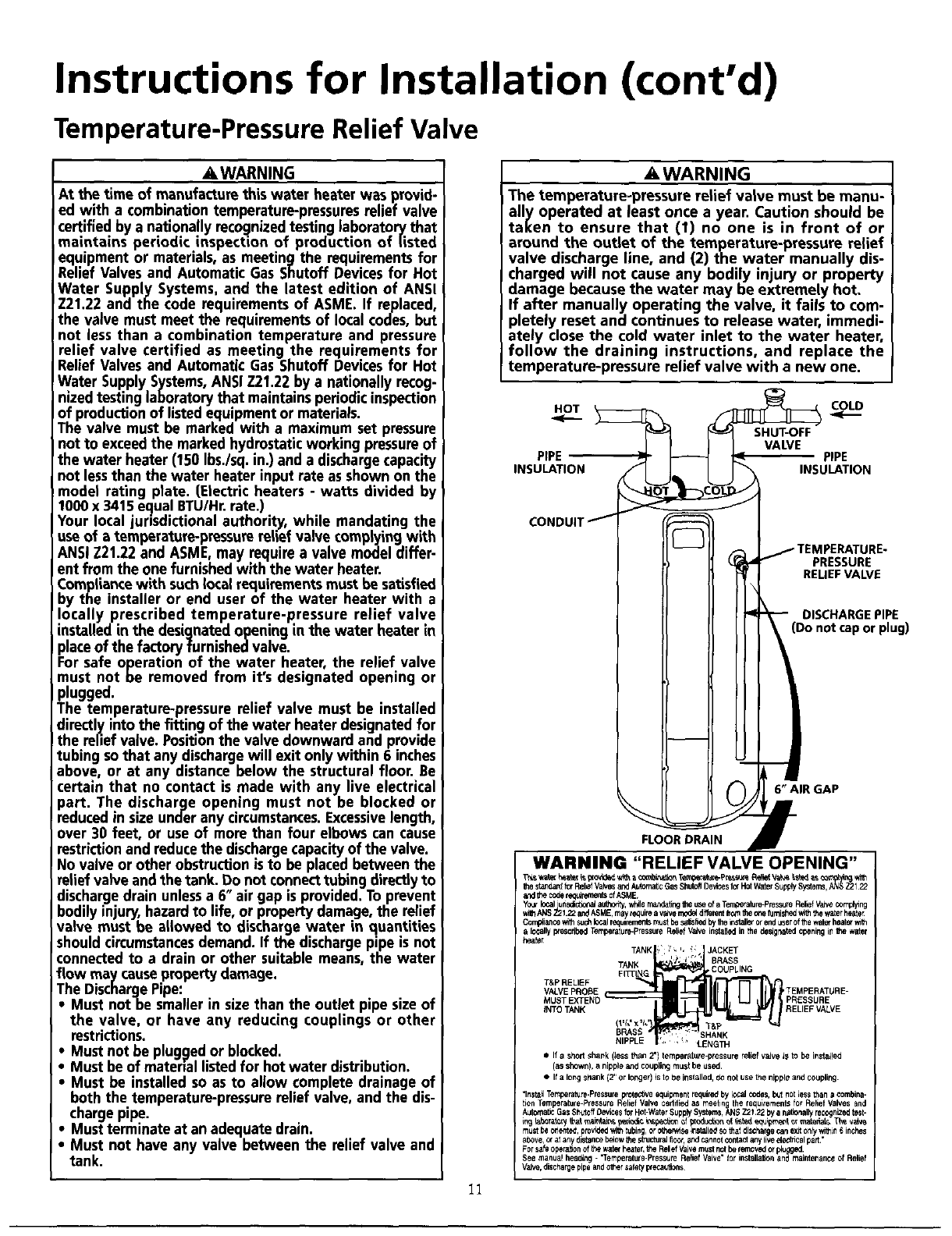
The temperature-pressure relief valve must be installed
directly intothe fitting of the water heater designatedfor
the relief valve. Positionthe valve downward and provide
tubing sothat any dischargewill exit only within 6 inches
above, or at any distance below the structural floor. Be
certain that no contact is made with any live electrical ( 6'_AIRGAP
part. The discharge opening must not be blocked or _ _ ml
r_luced in size under any circumstances.Excessivelength, _ _
r
over 30 feet, or useof more than four elbows can cause FLOORDRAIN
restrictionand reducethe dischargecapacityof the valve.
No valve or other obstruction is to be placed between the WARNING "RELIEF VALVE OPENING"
relief valve and the tank. Do not connecttubing directly to T_._ _._o_._T_P_ _v_ ._
Ibesta_ forRelCfVak_sandAutoma_cGasShUtOffDevicesforHotWaterSupPlySy_i_s_,_1 22
discharge drain unless a 6" air gap is provided. To prevent andlt_codereo_rementsofASME,
ANSI_ 122 andASME,mayrequirearave rnc_ dC_ferenttrc_nthec_efurnishedwilhthewaterheate_bodilyinjury,hazard to life, or property damage, the relief Yo_ localunsctct_w,aJ_ wr_lerna_Ung _ useof aTer_ture-Pressule ReliefVaIWcomplying
valve must be allowed to dischargewater in quantities C_rn_ianc_i1hsuch_a_r_qu_rementsr_ustbes_tis_edby1be_ta_renduser_w_h_=_a locallypcescribedTerrperature-PressureReliefVaJveinsialJedinthe bes_ghatedopeningi_1hewater
should circumstancesdemand. If the dischargepipe is not _r
connectedto a drain or other suitable means,the water
TANK, %', _" JACKET
TANK • l- BRASS
flow may causepropertydamage. FnT_G COUPLING
The DischargePipe: T&P RELIEF _i&_
VALVE PROBE TEMPERATURE-
MUST EXTEND PRESSURE
• Must notbe smallerin sizethan the outlet pipe size of
INTOTANK RELIEF VALVE
the valve, or have any reducing couplings or other i_, _t
' SHANK
restrictions. _ [_ _ _GTH
• Must not be pluggedor blocked. • Ifa shortshank (Jessthan 2') temperature-pressurereliefvalve isto be instated
• Must be of material listedfor hot water distribution. (asshown),anippleandcouplingmustbeused
• iust be installed so as to allow cornplete drainage of • ifalongs_lank(2" orlonger)isto be installed,donot usethe nippleand coupling.
both the temperature-pressure relief valve, and the dis- ",r,_ Temperalure.Pressureprotectiveequipmentrequiredbylocalcodes,b_tnotlessthan a combina-
tionTemperatule-PressureRelief Valve Cedriiedas meetingthe requbemenlSfor ReliefValves and
charge pipe. A_o_=_ GasShttoffDevicesforHot-Wat0rSupplySystems,AN_Z2_22 byanJt_nallyrecognLzedtest-
• Must terminate at an adequatedrain, mustbec_ented.pmv_edwi_tubing,or0the_iseinstabeds01hatdischa_ecanex_onFfwii_in6incbes
• Must not have any valve between the relief valve and above,ofatanydlstancebdowtbestrdcturaJflcot,a_dcannotcontactanyflveei_icalpa,."
Forsafe0bera_n ofthewsle_heater,b_eReliefVaJvemustnotbe lem0vedorp_u ed.
tank, Seemanualheading- "Ternperatule-Pre_sure ReliefValve"for installabonan_gmeaintenanceof Relief
VaJv_,dischargepipeandothersafetywecautJ0ns
11


